Brakes
The Brakes page configures your vehicle's braking system, including torque distribution, torque limits, pressure calculation, and individual caliper specifications. The brake system is modular — you choose which aspects to model in detail depending on your available data.
Component Structure
The brake system consists of a Brakes component and up to four Caliper components. Brakes and Calipers are independent library items — each can be saved, loaded, and shared separately.
graph TD
    B["<b>Brakes</b><br/><i>Bias + Limit Mode + Pressure Mode</i>"]
    FL["<b>FL Caliper</b><br/><i>Pistons, Disc, Pad</i>"]
    FR["<b>FR Caliper</b><br/><i>Pistons, Disc, Pad</i>"]
    RL["<b>RL Caliper</b><br/><i>Pistons, Disc, Pad</i>"]
    RR["<b>RR Caliper</b><br/><i>Pistons, Disc, Pad</i>"]

    B --> FL
    B --> FR
    B --> RL
    B --> RR

    style B fill:#6366f1,color:#fff
    style FL fill:#10b981,color:#fff
    style FR fill:#10b981,color:#fff
    style RL fill:#f59e0b,color:#fff
    style RR fill:#f59e0b,color:#fff
The four caliper positions correspond to:
| Position | Label (Symmetry Off) | Label (Symmetry On) |
|---|---|---|
| Front Left | FL Caliper | Front Caliper |
| Front Right | FR Caliper | (disabled) |
| Rear Left | RL Caliper | Rear Caliper |
| Rear Right | RR Caliper | (disabled) |
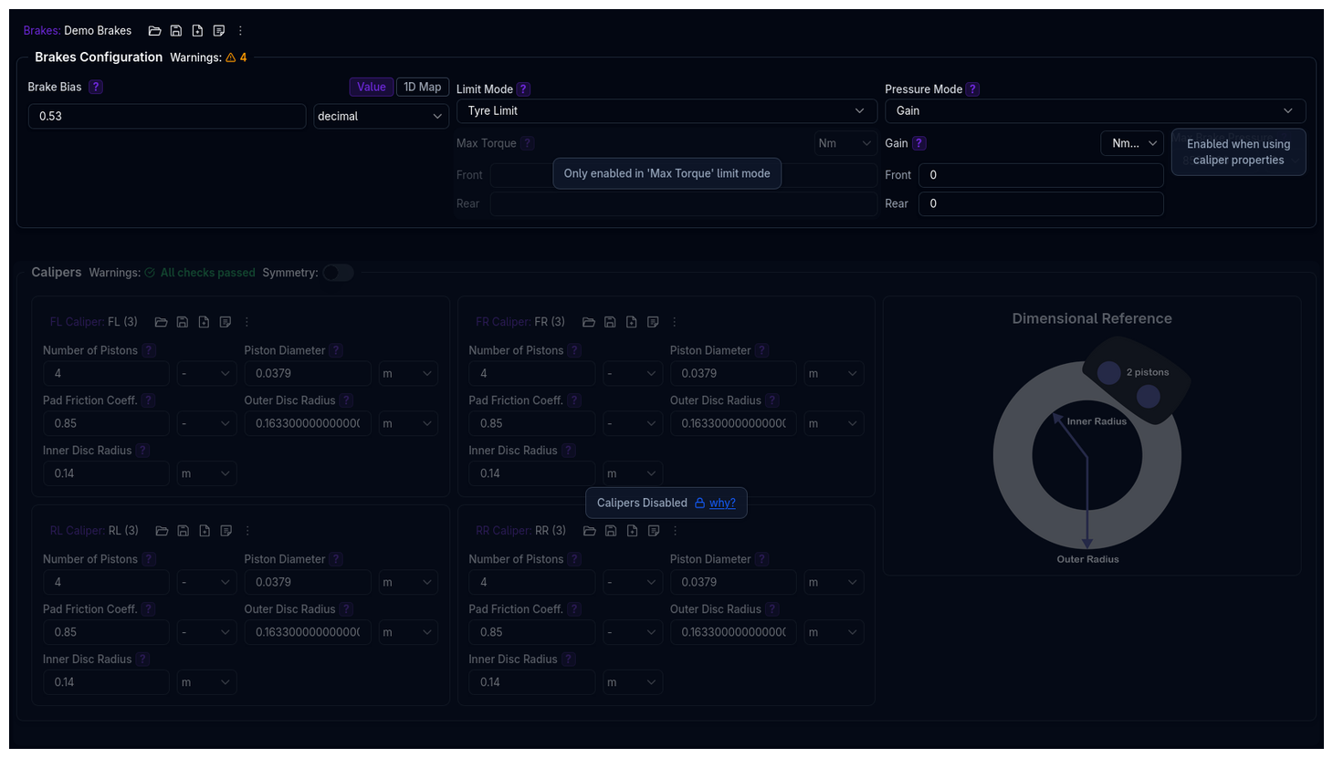
Page Layout
The Brakes page is divided into two main sections:
- Brakes Configuration — Brake bias, limit mode, and pressure mode
- Calipers — Individual caliper specifications for all four corners
Brakes Configuration
The Brakes Configuration section is laid out as a three-column grid:
Brake Bias
Determines the percentage of total braking torque directed to the front axle, assuming symmetrical left-right distribution. A bias of 0.6 means 60% of braking torque goes to the front axle and 40% to the rear.
Supported data types:
- Value — A single constant bias (e.g.,
0.6) - 1D Map — Bias as a function of vehicle speed (X-axis: Vehicle Speed, Y-axis: Brake Bias)
See Data Types for details on each mode.
Valid range: 0 to 1 (0 = all rear, 1 = all front)
Typical Values
Most racing vehicles use a front bias between 0.55 and 0.70. Values above 0.8 or below 0.4 will trigger a validation warning.
Limit Mode
Defines how the maximum brake torque is determined for each axle. This controls the upper bound of braking force the system can produce.
| Mode | Description |
|---|---|
| Tyre Limit | No hardware limit — braking torque is only limited by tyre grip. This is the simplest mode and the default. |
| Max Torque | User-defined maximum torques for front and rear axles. The simulation will not exceed these values regardless of available grip. |
| Caliper Properties | Maximum torque is calculated from caliper geometry, pad friction, and maximum brake pressure. Requires caliper data to be configured. |
Max Torque Sub-Parameters
When Limit Mode is set to Max Torque, the following fields become available:
| Parameter | Description | Unit |
|---|---|---|
| Front Max Torque | Maximum braking torque for the front axle | Nm |
| Rear Max Torque | Maximum braking torque for the rear axle | Nm |
These fields are disabled when any other limit mode is selected.
Tip
The actual torque applied during simulation depends on tyre and track grip levels, but will not exceed this user-defined value.
Pressure Mode
Defines how brake pressure is calculated from braking torque. This is primarily used for output channel calculations (e.g., displaying brake pressure in results).
| Mode | Description |
|---|---|
| Gain | Uses front and rear gain values to convert between torque and pressure. The gain represents the relationship between brake line pressure and wheel torque. |
| Caliper Properties | Pressure is calculated from caliper geometry — piston area, number of pistons, pad friction, and effective disc radius. Requires caliper data to be configured. |
Gain Sub-Parameters
When Pressure Mode is set to Gain, the following fields become available:
| Parameter | Description | Unit |
|---|---|---|
| Front Gain | Torque-to-pressure ratio for the front axle | Nm/bar |
| Rear Gain | Torque-to-pressure ratio for the rear axle | Nm/bar |
Note
The gain is used for output channel calculations and does not influence the simulation itself.
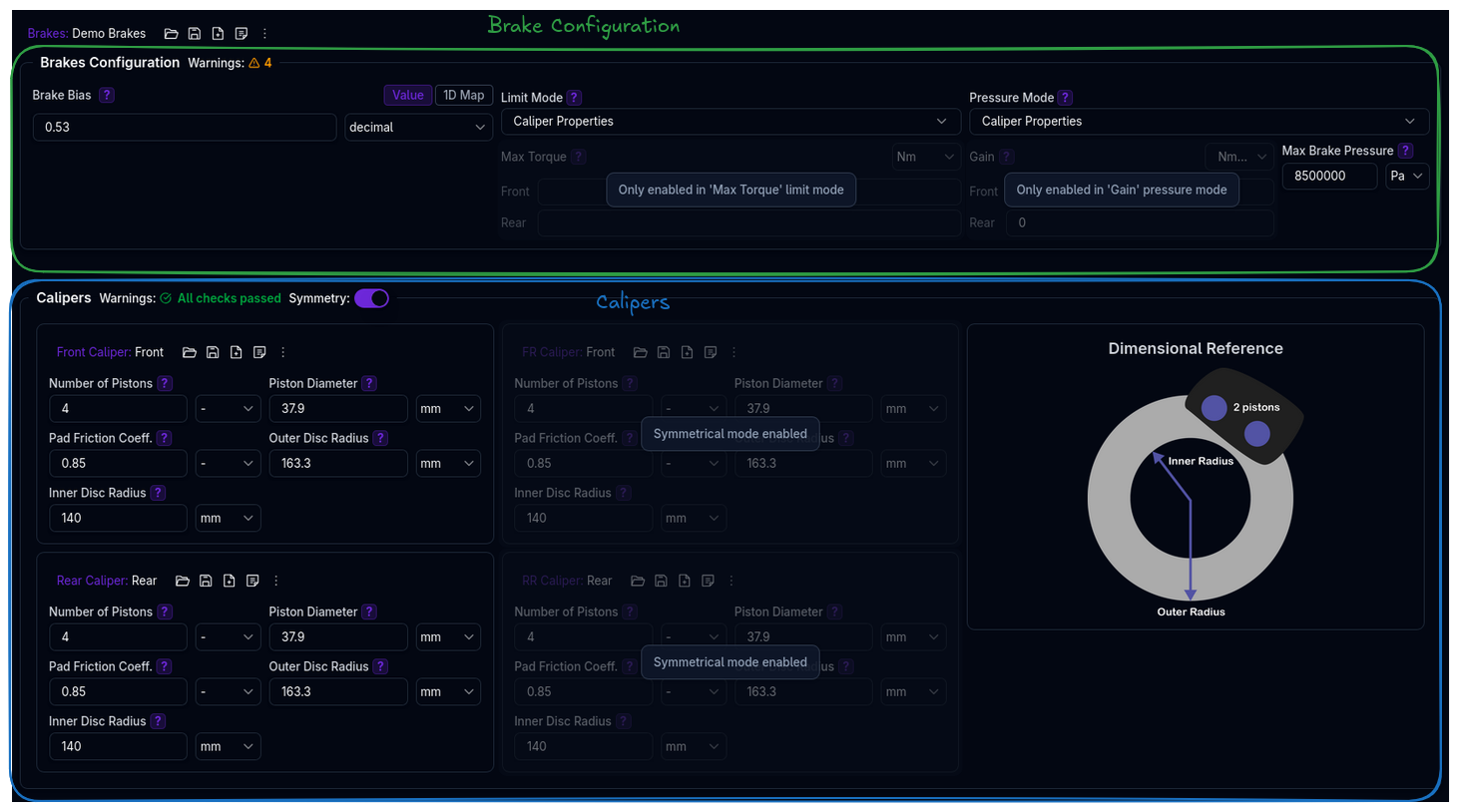
Max Brake Pressure
When either Limit Mode or Pressure Mode is set to Caliper Properties, the Max Brake Pressure field becomes available:
| Parameter | Description | Default | Unit |
|---|---|---|---|
| Max Brake Pressure | The maximum pressure applied to the brake system | 8,500,000 | Pa |
This value is used together with caliper specifications to calculate maximum hardware torque limits.
Calipers
The Calipers section is only enabled when at least one of Limit Mode or Pressure Mode is set to Caliper Properties. Otherwise, the entire section is greyed out with an explanatory message.
Symmetry
A Symmetry toggle in the Calipers section header controls left-right symmetry:
- Symmetry On: Only the left-side calipers (Front and Rear) are editable. Right-side values mirror the left automatically. The labels change to "Front Caliper" and "Rear Caliper".
- Symmetry Off: All four corners (FL, FR, RL, RR) are independently configurable.
Caliper Parameters
Each caliper has five parameters:
| Parameter | Description | Unit |
|---|---|---|
| Number of Pistons | The number of pistons in the caliper. Affects total piston area and braking force. | - |
| Piston Diameter | The diameter of each piston. Larger pistons produce more clamping force for a given pressure. | m |
| Pad Friction Coefficient | The coefficient of friction between the brake pads and disc. Determines braking effectiveness. | - |
| Outer Disc Radius | The radius of the outer edge of the brake disc. | m |
| Inner Disc Radius | The radius of the inner edge of the brake disc. Must be smaller than the outer radius. | m |
A Dimensional Reference diagram is displayed alongside the caliper fields showing the disc geometry (outer and inner radii).
Caliper Library Management
Each caliper is an independent library component with its own command palette. You can:
- Save a caliper configuration to the library
- Load a saved caliper from the library
- Duplicate a caliper configuration
- Lock/Hide calipers for team collaboration
When multiple caliper positions reference the same library item (same ID), editing one will automatically sync changes to all positions sharing that item.
How Brake Torque is Calculated
Understanding how the different modes interact helps you choose the right configuration for your data.
Torque Distribution
The total brake torque demand is split between front and rear axles using the bias:
Torque Limiting
The maximum torque each axle can produce depends on the Limit Mode:
- Tyre Limit: No cap — the simulation uses whatever torque the tyres can sustain.
- Max Torque: Capped at the user-defined front and rear values.
- Caliper Properties: Calculated as:
where the sum is over both calipers on the axle (left + right), and:
Piston Area      = π × (Piston Diameter / 2)²
Effective Radius = (Outer Disc Radius + Inner Disc Radius) / 2
Pressure Calculation
Brake pressure is derived from torque using the Pressure Mode:
- Gain:
Pressure = Torque / Gain(converted from bar to Pa) - Caliper Properties:
Pressure = Torque / Axle Gain, where the axle gain is computed from the caliper geometry as described above.
Validation Warnings
The platform validates brake configurations and reports non-critical warnings.
Brake System Warnings
| Condition | Warning |
|---|---|
| Bias > 0.8 | Very high front brake bias may decrease braking performance |
| Bias < 0.4 | Very low front brake bias may decrease performance and cause instability |
| Mismatched left/right caliper areas on same axle | Uneven braking may result |
| Caliper area distribution differs from bias by > 10% | Hardware proportions don't match the specified torque bias |
| Max brake pressure < 1 MPa | Low pressure may limit braking performance |
| Max brake pressure > 15 MPa | Very high pressure — verify system specifications |
Caliper Warnings
| Condition | Warning |
|---|---|
| Inner-to-outer disc radius ratio > 0.9 | Very thin brake ring with minimal effective area |
| Inner-to-outer disc radius ratio < 0.2 | Unusually wide brake ring with pressure distribution issues |
| Piston-to-disc area ratio > 0.5 | Piston area unrealistically large compared to disc |
| Piston-to-disc area ratio < 0.02 | Very high pressures needed for adequate braking |
| Number of pistons > 8 | Exceeds typical racing caliper configurations |
| Pad friction coefficient > 0.8 | Exceeds typical racing compound specifications |
| Pad friction coefficient < 0.15 | Below basic street pad specifications |
| Piston diameter > 65 mm | Exceeds typical racing caliper specifications |
| Piston diameter < 15 mm | Below practical manufacturing limits |
| Outer disc radius <= inner disc radius | Invalid geometry |
Mode Selection Guide
graph TD
    Q1{What data<br/>do you have?}
    Q1 -->|"No hardware specs"| TL["<b>Tyre Limit</b> + <b>Gain</b><br/>Simplest — only need bias and gain values"]
    Q1 -->|"Axle torque limits"| MT["<b>Max Torque</b> + <b>Gain</b><br/>Define front/rear max torques"]
    Q1 -->|"Full caliper specs"| CP["<b>Caliper Properties</b><br/>for both Limit and Pressure modes"]

    style TL fill:#10b981,color:#fff
    style MT fill:#6366f1,color:#fff
style CP fill:#f59e0b,color:#fff| Scenario | Limit Mode | Pressure Mode |
|---|---|---|
| Quick setup, no caliper data | Tyre Limit | Gain |
| Known max torques from dyno testing | Max Torque | Gain |
| Full caliper specifications available | Caliper Properties | Caliper Properties |
| Caliper specs for limits, gain for pressure output | Caliper Properties | Gain |
Tips
- Start with Tyre Limit + Gain if you don't have detailed caliper data — this is the simplest configuration
- Brake bias has a large effect on vehicle balance — higher front bias promotes understeer on corner entry, lower front bias promotes oversteer
- Use symmetry mode when left and right calipers are identical (most common configuration)
- Check the caliper area vs bias warning — if your calipers have significantly different front/rear sizing than your bias suggests, the system will flag this
Next Steps
- Configure Powertrain
- Test braking performance with Straight Line Simulation
- Review Lap Time Simulation to see braking zones in context