Chassis
 The Chassis component defines the reference measurements for your vehicle's mass properties, dimensions, and structural characteristics. These are the foundational parameters measured at a specific reference state (typically on a setup sheet or corner weight scales).
Reference vs Race-Ready State
The Chassis page defines reference measurements (where pickup points and CG were measured), while the Initialization page defines the actual race-ready state used in simulations. The platform automatically adjusts CG and inertias based on differences between the two.
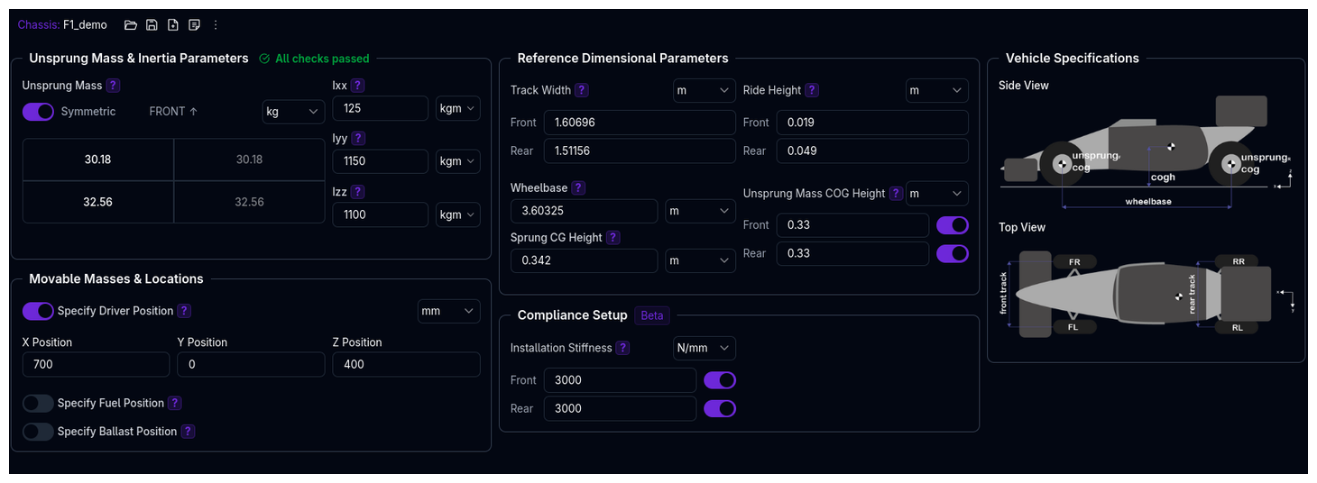
Overview
The Chassis setup defines:
- Unsprung Mass & Inertia - Mass at each corner not supported by suspension, plus sprung inertias
- Movable Mass Locations - Optional positions for driver, fuel, and ballast (enables automatic CG/inertia recalculation)
- Reference Dimensions - Wheelbase, track widths, ride heights, and CG height measured at reference state
- Compliance Setup - Installation stiffness for advanced compliance modeling (BETA)
Unsprung Mass & Inertia Parameters
Unsprung Mass (Per Corner)
The mass of components not supported by suspension springs at each wheel (FL, FR, RL, RR).
Includes: - Wheel and tyre assembly - Brake components (disc, caliper, hub) - Uprights/knuckles - Lower suspension components (below spring mounting point)
Excludes: - Chassis - Driver, fuel, ballast - Upper suspension components (above spring mounting)
Typical values: - Formula cars: 25-35 kg per corner - GT/Prototype cars: 30-45 kg per corner - Touring cars: 40-55 kg per corner - Road cars: 50-70 kg per corner
Why Unsprung Mass Matters
Lower unsprung mass improves tyre contact with the road, enhancing grip, handling responsiveness, and ride quality. It's one of the most important factors for suspension performance.
Balance Between Corners
Large imbalances (>5 kg difference between left/right) can cause handling asymmetry. The platform will warn if imbalances are detected.
Sprung Inertias (Ixx, Iyy, Izz)
The moments of inertia of the sprung mass (excluding driver, fuel, and ballast) about the three vehicle axes.
Reference frame: Origin at center of gravity
- Ixx (Roll Inertia): Resistance to rotation about the longitudinal (x) axis
- Iyy (Pitch Inertia): Resistance to rotation about the lateral (y) axis
- Izz (Yaw Inertia): Resistance to rotation about the vertical (z) axis
Typical values:
| Vehicle Type | Ixx (kg·m²) | Iyy (kg·m²) | Izz (kg·m²) |
|---|---|---|---|
| Formula cars | 300-600 | 1000-2000 | 1200-2500 |
| GT/Prototype | 400-800 | 1500-2500 | 2000-3000 |
| Road cars | 500-900 | 2000-3500 | 2500-4000 |
Automatic Recalculation
If you specify positions for driver, fuel, and ballast in the Movable Masses & Locations section below, the platform automatically recalculates total vehicle inertias using the parallel axis theorem when these masses are added.
Measurement Units
Ensure inertias are in kg·m² (kilogram-meters squared). Common errors occur from unit confusion (e.g., using kg·mm²). The platform validates against expected ranges.
Movable Masses & Locations
Optional 3D coordinates for driver, fuel, and ballast positions. When specified, the platform automatically recalculates CG height and inertias when these masses are added in Initialization.
Coordinate System
Origin: Center of front axle at ground level
- X-axis: Positive toward rear (longitudinal)
- Y-axis: Positive toward left (lateral)
- Z-axis: Positive upward (vertical)
See Coordinate System for details.
Driver Position
Location of the driver's center of mass (including seat and safety equipment).
Example: - X: 1200 mm (1.2m behind front axle) - Y: 0 mm (centerline) - Z: 400 mm (0.4m above ground)
Fuel Position
Location of the fuel tank's center of mass.
Example: - X: 1500 mm (1.5m behind front axle) - Y: 0 mm (centerline) - Z: 200 mm (0.2m above ground)
Ballast Position
Location of ballast weight's center of mass.
Example: - X: 800 mm (0.8m behind front axle) - Y: -200 mm (200mm right of centerline) - Z: 50 mm (50mm above ground)
When to Specify Positions
Specifying positions enables accurate CG and inertia calculations as fuel burns off or ballast changes. If not specified, the platform uses the reference CG height for all conditions.
Measuring Positions
Measure from the center of the front axle at ground level. Use CAD models or physical measurements. Even approximate positions (±50mm) are better than none for fuel load sensitivity studies.
Reference Dimensional Parameters
These are the reference measurements defining the vehicle geometry and CG location.
Track Width (Front & Rear)
Distance between the centers of the left and right tyre contact patches at each axle.
Typical values: - Formula cars: 1.2-1.5 m - GT cars: 1.5-1.7 m - Touring cars: 1.5-1.8 m - Road cars: 1.4-1.6 m
Track Width Difference
Large differences between front and rear track (>20%) will trigger a warning. This is normal for some race cars but should be verified.
Ride Height (Front & Rear) - REFERENCE
The ride height at which the suspension kinematics pickup points and CG height were measured.
This is NOT the race-ready ride height (that's set in Initialization).
Example: - Chassis reference: Front 50mm, Rear 60mm (measurement condition) - Initialization actual: Front 45mm, Rear 55mm (race trim) - Platform automatically adjusts CG and kinematics by the 5mm difference
Why Two Ride Heights?
The Chassis reference ride height anchors the kinematics and CG measurements. The Initialization ride height is what's actually used in simulation. This separation allows you to measure kinematics once and then simulate different ride height settings.
Wheelbase
Distance between the front and rear axle centers.
Typical values: - Formula cars: 2.4-2.7 m - GT cars: 2.6-2.9 m - Touring cars: 2.7-3.1 m - Road cars: 2.5-2.8 m
Sprung CG Height
The height of the sprung mass center of gravity above ground, measured at the reference ride height.
Excludes: Driver, fuel, ballast (added separately in Initialization)
Typical values: - Formula cars: 250-350 mm - GT cars: 300-450 mm - Touring cars: 400-550 mm - Road cars: 450-600 mm
CG Height Measurement
See the Measurement Guide for detailed instructions on measuring CG height using corner weight scales and tilt tests.
Automatic Adjustment
When you change ride height in Initialization, the platform automatically adjusts this CG height value for the new ride height and recalculates inertias.
Unsprung Mass COG Height (Optional)
The height of the unsprung mass center of gravity at each axle. If not specified, defaults to the tyre radius.
Typical values: - Front: 250-350 mm - Rear: 250-350 mm
When to Specify
Only specify if you have measured data or detailed CAD. The tyre radius default is accurate enough for most applications.
Compliance Setup (BETA)
Advanced compliance modeling for suspension and chassis flex.
Installation Stiffness (Front & Rear)
The vertical stiffness of the suspension/chassis compound, acting like an additional spring in series with the wheel spring.
What it does: - Models compliance in suspension mounts, bushings, and chassis flex - Reduces effective wheel rate - Affects ride frequency and suspension response
Formula:
Typical values: - Stiff race car: 500-1000 N/mm per corner - Road car: 200-500 N/mm per corner
BETA Feature
Installation stiffness modeling is in beta. Use only if you have measured compliance data. For most applications, leave this disabled.
How Chassis Relates to Other Components
Initialization
The Initialization page uses Chassis reference measurements as the baseline:
- Reference ride height → Adjusts to actual race-ready height
- Reference CG height → Adjusted for ride height change and added masses
- Sprung inertias → Recalculated when driver/fuel/ballast added
Suspension
The Suspension kinematics are measured at the Chassis reference ride height. When the Initialization ride height differs, kinematics are automatically adjusted.
Results
Vehicle Metrics on the Initialization page show the calculated properties based on Chassis references plus current masses.
Configuration Workflow
Recommended Workflow
-
Start with a Vehicle Template
- Templates include realistic baseline chassis parameters
- Modify to match your specific vehicle
-
Enter Unsprung Masses
- Weigh each corner's unsprung components
- Include wheel, tyre, brake, hub, upright
- Aim for balance between left/right
-
Enter Sprung Inertias
- Use CAD data if available
- Or use typical values for your vehicle type
- Ensure units are kg·m²
-
Enter Reference Dimensions
- Measure wheelbase (axle center to axle center)
- Measure track widths (contact patch to contact patch)
- Measure reference ride heights (where kinematics measured)
- Calculate or measure CG height
-
Specify Movable Mass Positions (Optional)
- Measure driver, fuel, ballast positions from front axle center at ground
- Use CAD if available, or physical measurements
- Enables automatic CG/inertia recalculation
-
Configure Compliance (Optional, BETA)
- Only if you have measured installation stiffness data
- Leave disabled for most applications
-
Review Validation Warnings
- Check Tree View for warnings
- Address any flagged issues
- Warnings don't block simulation but indicate potential issues
Validation Warnings
The platform validates chassis parameters and warns for:
Unsprung Mass: - Total unsprung mass >35% of vehicle mass (severely degrades handling) - Left/right imbalance >5 kg per axle (causes handling asymmetry)
Geometry: - Track/wheelbase ratio <0.3 (very narrow, unstable) - Track/wheelbase ratio >1.2 (extremely wide, unusual) - Front/rear track difference >20% (verify intentional)
Center of Gravity: - CG height/wheelbase ratio >0.5 (very high, excessive roll)
Ride Height: - Minimum ride height <10 mm (ground clearance issues) - Front/rear difference >150 mm (large rake, verify intentional)
Inertias: - Ixx, Iyy, or Izz >5× expected (check units/calculations) - Ixx, Iyy, or Izz <0.1× expected (check units/calculations)
Expected Inertia Calculations
The platform estimates expected inertias based on vehicle dimensions and mass using simplified formulas. Large deviations suggest unit errors or calculation mistakes.
Viewing Warnings
Warnings appear in the Tree View next to the Chassis component. Click the warning icon to view details.
Tips & Best Practices
Measure Unsprung Mass Accurately
Weigh each corner's unsprung components separately. Small errors here significantly impact suspension natural frequency calculations. See the Measurement Guide.
Use CAD for Inertias
If you have a CAD model, export mass properties directly. This is far more accurate than estimation formulas.
Reference Ride Height vs Race Ride Height
Don't confuse Chassis reference ride height (measurement condition) with Initialization ride height (race condition). They serve different purposes.
Sprung Mass Excludes Driver/Fuel/Ballast
The sprung inertias should be measured without driver, fuel, or ballast. These are added separately in Initialization.
Related Topics
- Initialization Setup - Set race-ready masses, ride heights, and weight distribution
- Suspension Setup - Configure kinematics measured at chassis reference state
- Coordinate System - Understanding the coordinate frame for mass positions
- Component Hierarchy - How chassis relates to other components
- Measurement Guide - Detailed measurement instructions
Accurate chassis parameters are the foundation of realistic simulations. Invest time in precise measurements—your setup optimization depends on it.