Battery
The Battery component models the energy storage system for electric vehicles. It is only visible when the Power Source Type is set to Electric Vehicle on the Powertrain Overview.
The Battery is an independent library component — it can be saved, loaded, duplicated, and shared separately from the parent Powertrain.
Parameters
Cell Configuration
| Parameter | Description | Unit |
|---|---|---|
| Number of Cells in Series | Cells connected end-to-end to increase pack voltage | count |
| Number of Cells in Parallel | Cells connected side-by-side to increase pack capacity | count |
| Cell Capacity | Energy storage capacity of each individual cell | Ah |
Cell Configuration
- Series cells multiply voltage: Pack Voltage = Cell Voltage x Cells in Series
- Parallel cells multiply capacity: Pack Capacity = Cell Capacity x Cells in Parallel
State of Charge
| Parameter | Description | Unit |
|---|---|---|
| Starting State of Charge | Initial charge level of the battery pack (0 = empty, 1 = full) | decimal (0–1) |
Maximum Charge Power
| Parameter | Description | Unit |
|---|---|---|
| Max Charge Power | Maximum power the battery can accept through regenerative braking | W |
Set to 0 to disable regenerative braking entirely. For example, set to 50,000 for a 50 kW charge rate.
Electrical Characteristics
Single Cell Map (2D)
Defines cell voltage behaviour based on discharge rate and current draw. This is a 2D map:
- X-Axis: Discharge Rate (Ah) — how much capacity has been used
- Y-Axis: Amperage (A) — how much current is being drawn
- Z-Axis: Voltage (V) — resulting cell voltage under load
Higher current draw and deeper discharge both reduce cell voltage.
Internal Resistance (1D)
Models cell internal resistance as a function of state of charge:
- X-Axis: SOC (state of charge, 0–1)
- Y-Axis: Resistance (Ω)
Lower SOC typically results in higher internal resistance.
See Data Types for details on map editors.
Battery Visualisation
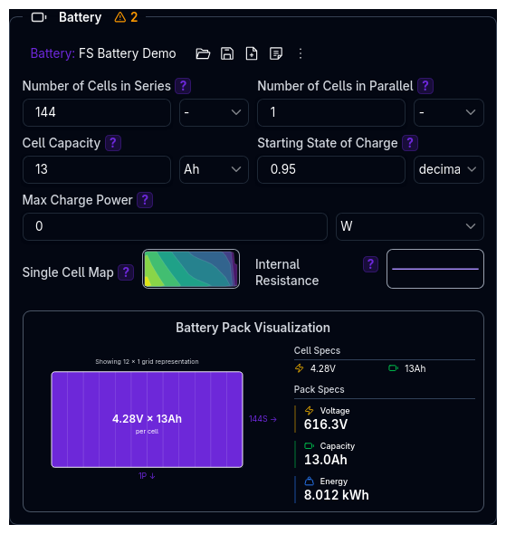
The component includes a real-time visualisation below the input fields showing:
- Pack Configuration — series/parallel cell arrangement
- Total Energy — usable energy storage in kWh
- Nominal Voltage — average operating voltage
- Cell Voltage — maximum cell voltage from the map
This helps verify your battery configuration at a glance.
Validation Warnings
Battery Warnings
| Condition | Warning |
|---|---|
| Cells in series < 80 | Low number of cells in series may result in low pack voltage |
| Cells in parallel > 20 | High number of cells in parallel |
| Pack energy < 1 kWh | Very low pack energy may severely limit range |
| Pack energy > 100 kWh | Very high pack energy — verify battery specifications |
| Nominal voltage < 100 V | Low nominal voltage may lead to high currents |
| Nominal voltage > 800 V | High nominal voltage requires specialised high-voltage components |
| Average cell resistance > 10 mΩ | High average cell resistance will lead to significant voltage drop |
Powertrain Integration Warnings
These warnings appear at the powertrain level when both battery and motor are configured:
| Condition | Warning |
|---|---|
| Motor max voltage > 95% of battery nominal voltage | Limited voltage headroom for motor performance |
| Motor max voltage < 70% of battery nominal voltage | Possible efficiency loss from voltage mismatch |
| Power-to-energy ratio > 50 | May lead to rapid battery depletion |
| Power-to-energy ratio < 5 | Oversized battery for power requirements |
Tips
- Match battery to motor — ensure pack voltage provides adequate headroom above the motor's operating voltage
- Set regenerative limits realistically — max charge power should reflect what the battery chemistry can safely accept
- Use the visualisation to verify pack energy and voltage before running simulations
- Paste data from spreadsheets — both the cell map and resistance map editors support paste from Excel or Google Sheets
Next Steps
- Configure Electric Motor to match battery voltage and power capabilities
- Set up Gears to optimise motor operating range
- Configure Efficiency to model system losses
- Return to Powertrain Overview