Engine
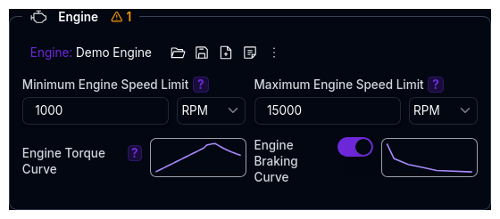
The Engine component configures the internal combustion engine (ICE) power source. It is only visible when the Power Source Type is set to Internal Combustion Engine on the Powertrain Overview.
The Engine is an independent library component — it can be saved, loaded, duplicated, and shared separately from the parent Powertrain.
Parameters
The Engine section contains two rows of parameters:
RPM Limits
| Parameter | Description | Default | Unit |
|---|---|---|---|
| Minimum Engine Speed Limit | The lowest RPM the engine can operate at. Defines the lower bound of the operating range. | 0 | RPM |
| Maximum Engine Speed Limit | The highest RPM the engine can reach. Limits engine speed and defines the upper bound for gear shift calculations. | 10,000 | RPM |
Max RPM must be greater than min RPM.
Torque Curves
Both curves are defined as 1D Maps (RPM vs Torque). Click the map thumbnail to open the editor.
| Parameter | Description | X-Axis | Y-Axis |
|---|---|---|---|
| Engine Torque Curve | The positive torque output at each RPM point. This is the primary performance curve of the engine. | RPM | Torque (Nm) |
| Engine Braking Curve | The negative torque (engine braking / back-torque) at each RPM point. Optional — if not provided, engine braking is zero. | RPM | Braking Torque (Nm) |
Engine Braking
The engine braking curve represents drag torque when the driver is off-throttle (e.g., compression braking). Values should be negative or zero. If not configured, the simulation assumes no engine braking effect.
How Engine Torque is Used
The engine provides a base torque at a given RPM. This torque flows through the drivetrain:
Engine Torque (at RPM)
    → × Efficiency (if enabled)
    → × Gear Ratio × Final Drive × Bevel Ratio
    → Wheel Torque
The simulation determines the operating RPM from vehicle speed, gear ratio, final drive, bevel ratio, and rolling radius:
The RPM is clamped between the min and max RPM limits. Outside this range, the engine cannot produce torque.
Power Curve
The platform automatically derives the power curve from the torque curve:
This is used internally for peak power calculations and is not directly editable.
Validation Warnings
| Condition | Warning |
|---|---|
| Operating range < 3,000 RPM | Narrow range may limit performance |
| Operating range > 10,000 RPM | Very wide range — verify specifications |
| Torque curve variation < 20% | Unusually flat torque curve — check engine data |
| Max RPM < 2× min RPM | Narrow RPM spread may limit performance |
| Min RPM below lowest torque map RPM | Min RPM extends below the defined torque data |
Tips
- Start with the torque curve — this is the most important parameter. If you have dyno data, enter the RPM and torque columns directly using the map editor (paste from Excel or Google Sheets)
- Set RPM limits to match your data — the min and max RPM should align with the range of your torque curve. If the min RPM is below the lowest torque map point, the simulation will extrapolate
- Engine braking is optional — for most lap time simulations, omitting it is acceptable. It becomes more relevant for transient simulations where off-throttle behaviour matters
- The engine is shared across setups — since it's an independent library item, changing it will affect all powertrains that reference the same engine
Next Steps
- Configure Gears for transmission ratios and shift strategy
- Configure Efficiency for drivetrain loss modelling
- Return to Powertrain Overview for the full system architecture