Tyres
Configure tyre dynamics and force models for all four corners of your vehicle. Define tyre characteristics, upload Pacejka Magic Formula coefficients, and tune grip behaviour.
Overview
The Tyres setup defines:
- Tyre Set - Assignment of individual tyre models to each corner
- Dynamics Properties - Vertical stiffness, damping, radius characteristics, and rotational inertia
- Force Models - Pacejka Magic Formula coefficients for longitudinal and lateral force generation
- Symmetry Modes - Front and rear symmetry options to simplify setup
- Grip Tuning - Global grip factor for scaling tyre forces
Tyre Models and Tyre Sets
A Tyre Model is a single library component containing all physical properties — dynamics (inertia, radii, rate, damping), force model (Pacejka coefficients), and grip factor. A Tyre Set assigns four tyre models (one per corner) to your vehicle. Multiple corners can share the same tyre model.
Understanding Tyre Models
What is a Tyre Model?
A tyre model is a single component that contains everything about a tyre:
- Dynamics properties - Inertia, loaded radius, rolling radius, tyre rate, tyre damping rate
- Force model - Pacejka Magic Formula type and all coefficients
- Grip factor - Global force multiplier
These are all stored together as one unit. You cannot assign separate dynamics and force models to the same corner — they are always part of the same tyre model.
Pacejka Magic Formula
The platform supports three versions of the Pacejka tyre model:
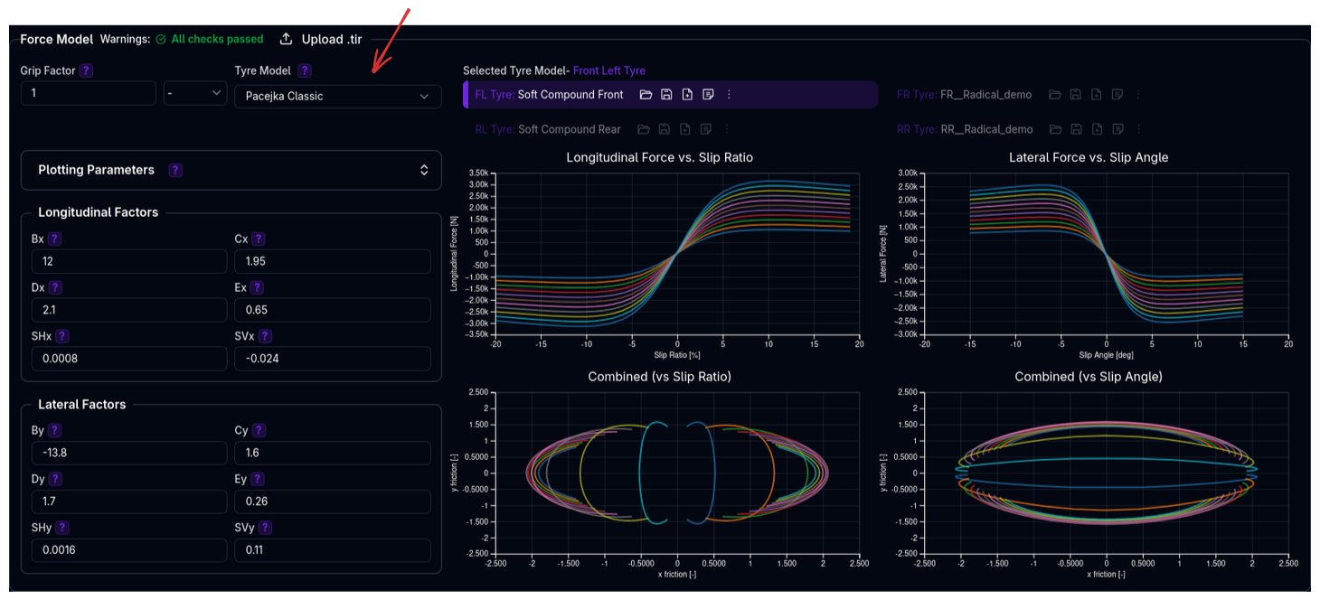
- Pacejka Classic - Simplified model for basic applications
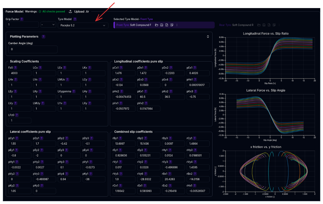
 - Pacejka 5.2 - Industry-standard model with comprehensive slip behaviour
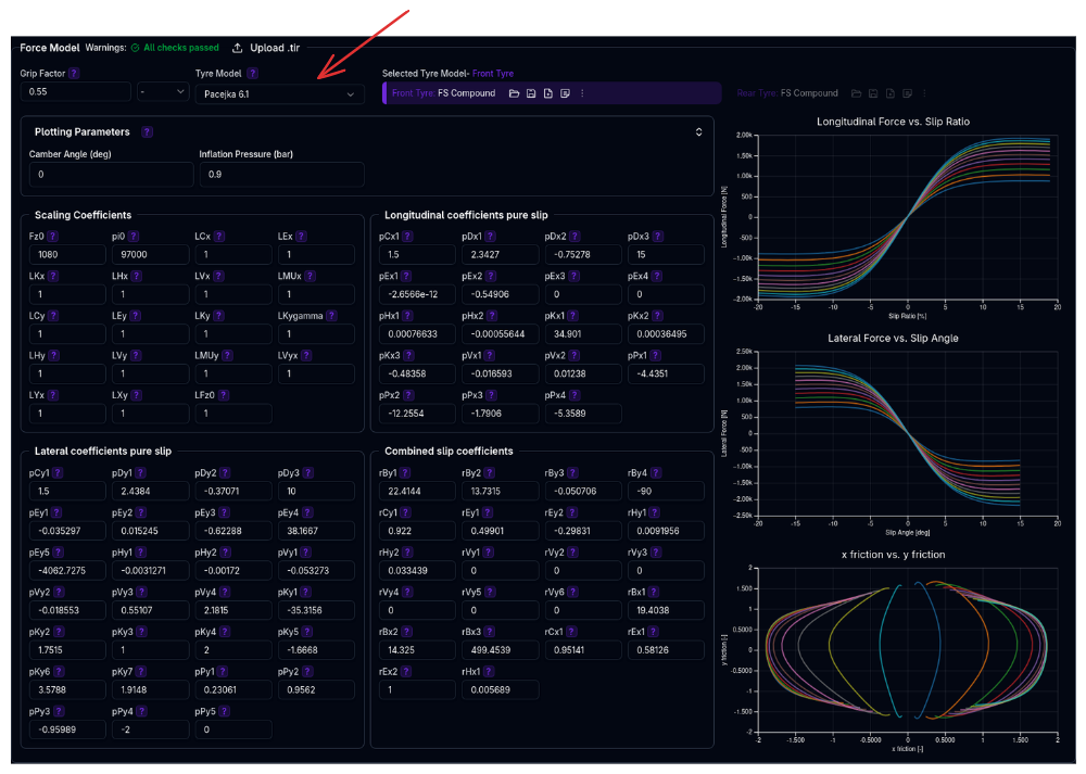
 - Pacejka 6.1 - Advanced model with inflation pressure effects
Why It Matters
Tyre models directly impact:
- Grip levels - Maximum lateral and longitudinal forces
- Slip behaviour - How forces build with slip angle and slip ratio
- Load sensitivity - Force changes with vertical load
- Ride quality - Vertical stiffness affects suspension response
- Longitudinal dynamics - Rolling radius affects speed calculations
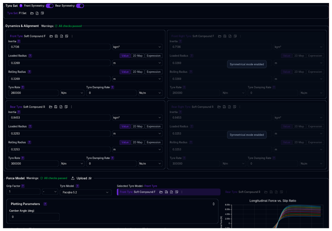
Tyres Page Structure
The Tyres page has three main sections:
1. Tyre Sets Section
Top of page: - Select which tyre model is assigned to each corner - Enable/disable front and rear symmetry - Manage tyre model library (create, duplicate, delete)
2. Dynamics & Alignment Section
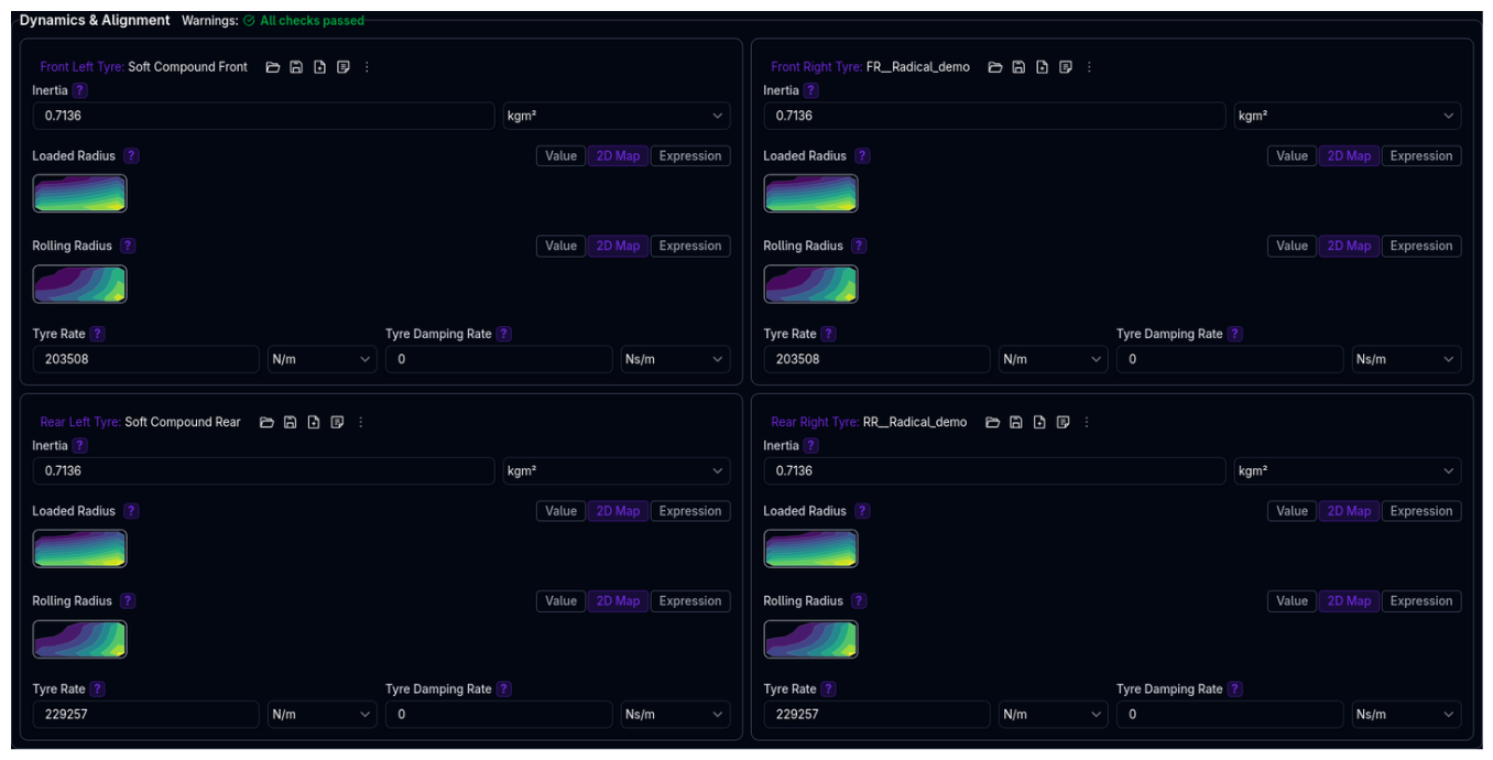
Four-corner grid (2×2 layout): - Configure vertical dynamics for each corner - Parameters: Inertia, Loaded Radius, Rolling Radius, Tyre Rate, Tyre Damping Rate - Automatically syncs when multiple corners use the same tyre model - Right side (FR, RR) disabled when symmetry is enabled
3. Force Model Section
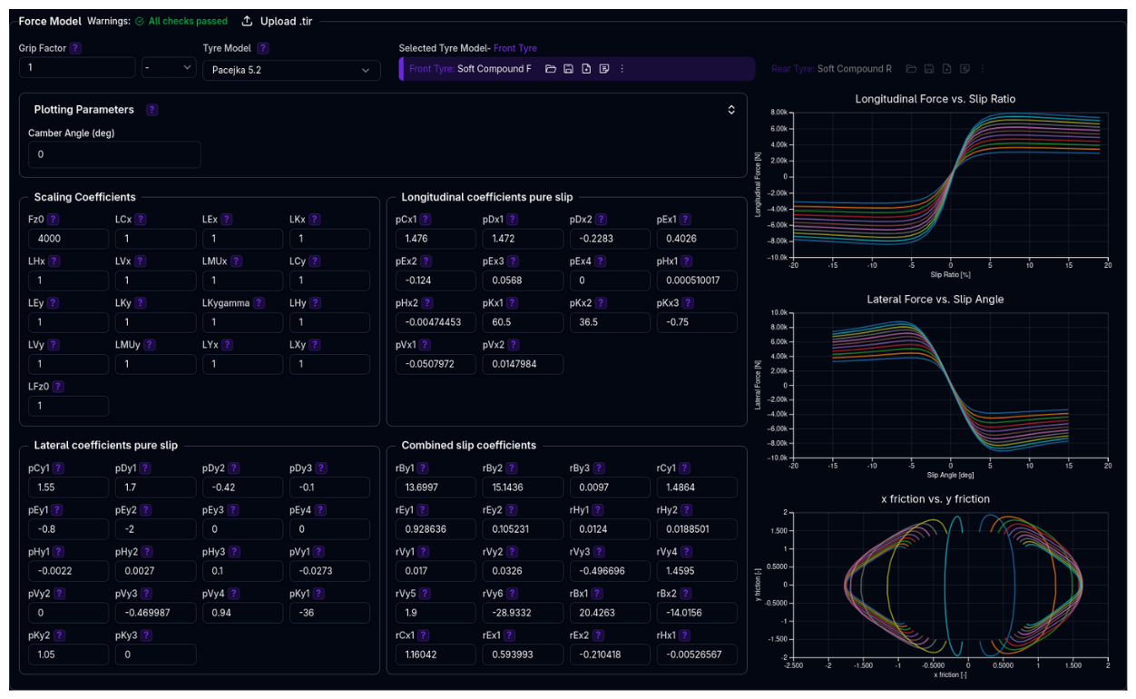
Single panel with corner selector: - Configure Pacejka coefficients for the selected corner - Choose tyre model type (Pacejka Classic / 5.2 / 6.1) - Upload .TIR files to import coefficients - Live preview charts showing force characteristics - Grip factor adjustment
Understanding the Tyre Set Structure
The Tyres setup uses a parent-child structure where the Tyre Set assigns individual tyre models to each corner, with optional symmetry linking left/right tyres.
graph TD
    TS[Tyre Set<br/>Front/Rear Symmetry Options]
    TS -->|Front Left| FL[FL Tyre Model<br/>Dynamics + Force + Grip]
    TS -->|Front Right| FR[FR Tyre Model<br/>Dynamics + Force + Grip]
    TS -->|Rear Left| RL[RL Tyre Model<br/>Dynamics + Force + Grip]
    TS -->|Rear Right| RR[RR Tyre Model<br/>Dynamics + Force + Grip]

    style TS fill:#6366f1,color:#fff
    style FL fill:#10b981,color:#fff
    style FR fill:#10b981,color:#fff
    style RL fill:#10b981,color:#fff
    style RR fill:#10b981,color:#fff
Each Tyre Model is a single component containing:
| Property | Description |
|---|---|
| Inertia | Rotational inertia of wheel+tyre |
| Loaded Radius | Radius under vertical load (Value, Map2D, or Expression) |
| Rolling Radius | Effective rolling radius (Value, Map2D, or Expression) |
| Tyre Rate | Vertical stiffness |
| Tyre Damping Rate | Vertical damping |
| Force Model Type | Pacejka Classic, 5.2, or 6.1 |
| Tyre Coefficients | All Pacejka coefficients |
| Grip Factor | Global force multiplier |
Key behaviours:
- Tyre Set (Parent) assigns tyre models to each corner and manages symmetry
- Tyre Models (Children) are self-contained — dynamics, force model, and grip are all part of the same model
- Symmetry: When enabled, right-side tyres mirror left-side configuration
- Shared Models: Multiple corners can reference the same tyre model (same ID), causing automatic syncing of all properties
Example: - Front symmetry enabled: FR uses same model as FL - Both front tyres use "Hoosier_18x10_R25B" (ID: 42) - Editing FL's grip factor or any dynamics parameter instantly updates FR - Rear tyres use a different model "Hoosier_20x12_R25B" (ID: 43)
Component Hierarchy
See Component Hierarchy for more details on how parent-child relationships work throughout ARD.
Tyre Symmetry

Front Symmetry
When enabled: - Front right tyre (FR) uses the same model and parameters as front left (FL) - FR configuration panel is disabled and shows "Symmetrical mode enabled" - Changes to FL automatically apply to FR
Rear Symmetry
When enabled: - Rear right tyre (RR) uses the same model and parameters as rear left (RL) - RR configuration panel is disabled and shows "Symmetrical mode enabled" - Changes to RL automatically apply to RR
When to Use Symmetry
Enable symmetry for conventional race cars with left-right symmetrical setups. Disable for oval racing or vehicles with deliberate left-right stagger.
Dynamics & Alignment Parameters
Inertia
Description: Rotational inertia of the wheel and tyre assembly.
Units: kg·m²
Typical Values: - Formula car: 0.5 - 1.2 kg·m² - GT car: 1.0 - 2.5 kg·m² - Prototype: 0.8 - 2.0 kg·m²
Impact: Affects wheel spin-up/spin-down response and longitudinal dynamics.
Validation: - ⚠️ Very low (<0.1 kg·m²) or high (>5 kg·m²) values will generate warnings
Understanding Loaded vs Rolling Radius
Before configuring radius parameters, it's important to understand the difference:
Loaded Radius: - The vertical distance from the wheel center to the ground under load - Changes with vertical load (tyre compresses) - Used for calculating ride height and suspension geometry - Physically measured at the center of the contact patch
Rolling Radius:
- The effective radius for rolling motion (longitudinal dynamics)
- Used to calculate wheel speed: vehicle speed = wheel angular velocity × rolling radius
- Used to calculate slip ratio in force models
- Accounts for tyre deflection and belt movement patterns
- Typically 2-5% larger than loaded radius
Why They're Different: When a tyre rolls, the tread belt deforms both vertically and longitudinally. The contact patch is not directly under the wheel center due to these deformations, making the effective rolling radius slightly larger than the static loaded radius.
General Rule of Thumb
Rolling radius is typically ≥ loaded radius. While not strictly enforced by the platform, keeping this relationship helps ensure physically realistic behaviour.
Loaded Radius
The loaded radius supports three data type modes: Value, Map2D, and Expression. For a detailed explanation of each mode, see Data Types.
Value mode (recommended): Enter the tyre's unloaded radius. The platform automatically calculates load-dependent deflection:
Map2D mode: Provide a lookup table of loaded radius vs speed (m/s) and vertical load (N). Use when you have measured data from tyre testing.
Expression mode: Write a single mathematical formula using the available variables: load, speed, camber, pressure. For example:
Typical Values: - Formula car (13" rim): 0.26 - 0.29 m unloaded - GT car (18" rim): 0.30 - 0.34 m unloaded - Prototype (18" rim): 0.31 - 0.35 m unloaded - Touring car (17-18" rim): 0.29 - 0.33 m unloaded
Impact: Affects static ride height, suspension geometry (camber/toe curves), wheel travel calculations, and load transfer dynamics.
Validation: - ⚠️ Values <0.1 m or >0.5 m generate warnings (likely data entry error) - ⚠️ Map2D speeds >110 m/s (~396 km/h) generate warnings
Rolling Radius
The rolling radius uses the same three modes as loaded radius (Value, Map2D, Expression). See Data Types for details on each mode.
Value mode (recommended): Enter a constant effective rolling radius. Unlike loaded radius, this value does not automatically adjust for load — it remains fixed.
Typical Relationship:
Typical Values: - Formula car (13" rim): 0.27 - 0.30 m - GT car (18" rim): 0.31 - 0.35 m - Prototype (18" rim): 0.32 - 0.36 m
Impact: Critical for accurate wheel speed calculations, slip ratio computations, and longitudinal dynamics (acceleration, braking).
Validation: - ⚠️ Values <0.1 m or >0.5 m generate warnings - ⚠️ Map2D speeds >110 m/s generate warnings
Tyre Rate
Description: Vertical stiffness of the tyre carcass.
Units: N/m (or N/mm for display)
Typical Values: - Formula car slick: 150-250 N/mm (150,000-250,000 N/m) - GT car slick: 200-350 N/mm - Prototype slick: 180-300 N/mm - Road car: 100-200 N/mm
Impact: - Affects ride frequency and comfort - Influences load transfer response - Combines with spring rate for total vertical stiffness - Higher rates reduce tyre deflection
Validation: - ⚠️ <90 N/mm: "Very soft tyre rate. May affect handling precision." - ⚠️ >500 N/mm: "Very stiff tyre rate. May compromise ride quality." - ⚠️ Front left/right mismatch >10 kN/m generates warning - ⚠️ Rear left/right mismatch >10 kN/m generates warning
Tyre Damping Rate
Description: Vertical damping provided by the tyre carcass.
Units: N·s/m (or N·s/mm)
Typical Values: - 20-100 N·s/m (much lower than shock absorber damping) - Usually contributes 5-15% of total system damping
Impact: - Smooths high-frequency vibrations - Affects initial impact response - Usually less significant than shock absorber damping
Force Model Configuration
Grip Factor
Description: Global multiplier applied to all forces generated by the tyre model.
Range: 0.001 - 10.0 (typical: 0.8 - 1.2)
Use Cases: - 1.0 - Standard grip, use tyre model as-is - 0.8-0.95 - Simulate worn tyres or low-grip conditions - 1.05-1.2 - Simulate fresh tyres or high-grip track evolution
Impact: Scales both lateral and longitudinal forces equally.
Validation: - ⚠️ <0.6: "Low grip factor. May indicate degraded performance." - ⚠️ >1.4: "High grip factor. Verify tire performance claims."
Grip Factor vs Coefficient Changes
Grip factor is a quick multiplier for all forces. For more precise control of peak force, shape, or load sensitivity, edit the Pacejka coefficients directly.
Tyre Model Selection
Choose between three Pacejka model versions:
Pacejka Classic
Best for: - Simple applications - When detailed tyre data is unavailable - Educational or initial setup
Limitations: - No pressure effects - Simplified load sensitivity - Basic combined slip behaviour
Pacejka 5.2 (Most Common)
Best for: - Professional racing applications - Standard industry tyre testing data - Most .TIR files use this format
Features: - Comprehensive slip behaviour - Load sensitivity - Camber effects - Combined slip (lateral + longitudinal interaction)
Coefficients organized in groups: - Scaling coefficients - Shape factors - Peak factors - Curvature factors - Stiffness factors - Camber factors - Combined slip factors
Pacejka 6.1 (Advanced)
Best for: - High-fidelity applications - When inflation pressure data is available - Advanced tyre testing programs
Additional Features vs 5.2: - Pressure dependency: pPx1-4 (longitudinal) and pPy1-5 (lateral) coefficients - Enhanced lateral model: Additional pEy5, pKy4-7 coefficients for better camber modeling - Enhanced combined slip: rBy4, rBx3 for improved load/camber dependencies - Pressure parameter: pi0 (nominal inflation pressure in Pa)
Additional Coefficients (vs Pac52): - Longitudinal: pDx3, pPx1-4 (pressure effects) - Lateral: pEy5, pKy4-7, pPy1-5 (camber² and pressure effects) - Combined: rBy4, rBx3 (additional dependencies) - Scaling: LVyx (longitudinal effect on lateral vertical scaling)
Requirements: - Pressure-dependent coefficient data from testing - pi0 nominal pressure specification - Additional calibration effort for pressure effects
Uploading .TIR Files
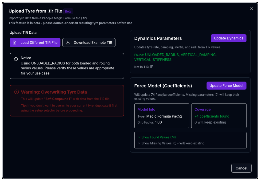
.TIR files contain Pacejka Magic Formula coefficients from tyre manufacturers or testing facilities. The upload dialog allows you to update both dynamics parameters and force model coefficients independently.
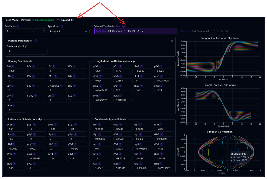
Quick Process:
- Click Upload .tir button in the Force Model section header
- Click Load TIR File and select your
.tirfile - Review the preview showing found/missing parameters
- Click Update Dynamics and/or Update Force Model as needed
Beta Feature
The .TIR upload is currently in beta. Please double-check all resulting tyre parameters before use.
For the full upload guide including file format details, troubleshooting, and tips, see Uploading .TIR Files.
Editing Pacejka Coefficients
Coefficient Organization
Pacejka coefficients are organized into groups by function. The naming convention uses prefixes to indicate the parameter type:
Scaling Coefficients (L prefix): - Fz0: Nominal wheel load (reference load for all calculations) - LCx, LCy: Shape factor scaling for longitudinal/lateral - LEx, LEy: Curvature factor scaling for longitudinal/lateral - LKx, LKy, LKygamma: Slip stiffness scaling - LHx, LHy: Horizontal shift scaling - LVx, LVy: Vertical shift scaling - LMUx, LMUy: Peak friction coefficient scaling - LXy, LYx: Combined slip scaling - LFz0: Nominal load scaling factor - These are the most commonly adjusted for calibration and quick force magnitude changes
Longitudinal Pure Slip Coefficients (p prefix + x): - pCx1: Shape factor - pDx1-2: Peak friction (nominal + load dependency) - pEx1-4: Curvature factors (nominal, load, camber, combined dependencies) - pHx1-2: Horizontal shift (nominal + load) - pKx1-3: Slip stiffness (maximum, load linear, load exponent) - pVx1-2: Vertical shift (nominal + load) - pPx1-4 (Pac61 only): Pressure effects on stiffness and peak
Lateral Pure Slip Coefficients (p prefix + y): - pCy1: Shape factor - pDy1-3: Peak friction (nominal, load, camber dependencies) - pEy1-5: Curvature factors (nominal, load, camber, load×camber, camber² - pEy5 is Pac61 only) - pHy1-3: Horizontal shift (nominal, load, camber) - pKy1-7: Cornering stiffness (maximum, load, camber, curvature, camber², camber factor, load×camber - pKy4-7 are Pac61 only) - pVy1-4: Vertical shift (nominal, load, camber, load×camber) - pPy1-5 (Pac61 only): Pressure effects on stiffness, load, peak, and camber
Combined Slip Coefficients (r prefix): - rBy1-4: Lateral force reduction slope (nominal, load, camber - rBy4 is Pac61 only) - rCy1: Lateral force reduction shape - rEy1-2: Lateral force reduction curvature (nominal + load) - rHy1-2: Lateral force reduction shift (nominal + load) - rVy1-6: Velocity-induced slip effects (various dependencies) - rBx1-3: Longitudinal force reduction slope (nominal, load - rBx3 is Pac61 only) - rCx1: Longitudinal force reduction shape - rEx1-2: Longitudinal force reduction curvature (nominal + load) - rHx1: Longitudinal force reduction shift
Where to Start When Tuning
- Scaling coefficients (L*) - Quickest way to adjust overall force levels
- Peak factors (pDx, pDy) - Set maximum force capability
- Stiffness factors (pKx, pKy) - Adjust initial force build-up
- Shape/curvature (pCx, pCy, pEx, pEy) - Fine-tune curve shape
- Combined slip (r*) - Adjust performance under combined braking/cornering
Live Preview Charts
When editing coefficients, three charts update in real-time:
1. Longitudinal Force vs Slip Ratio
Shows traction and braking force generation across different slip ratios.
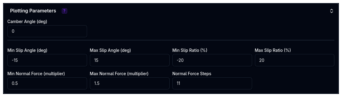
Chart controls: - Slip ratio range (min/max %) - Normal force multiplier range - Number of load steps
2. Lateral Force vs Slip Angle
Shows cornering force generation across different slip angles.
Chart controls: - Slip angle range (min/max degrees) - Camber angle (degrees) - Normal force multiplier range - Inflation pressure (Pac61 only, bar)
3. X Friction vs Y Friction (Friction Circle)
Shows combined slip behaviour - how tyre forces degrade when both longitudinal and lateral slip are present.
Interpretation: - Perfect circle = no combined slip effect - Compressed shape = realistic combined slip reduction - Shape reveals tyre's performance in combined braking/cornering
Plotting Parameters
The plotting parameters (slip ranges, camber, pressure) only affect the preview charts on this page. They are not saved and have no impact on simulations.
Corner Selection and Syncing
Selecting a Corner
Use the corner selector buttons in the Force Model section to choose which tyre to configure: - FL - Front Left - FR - Front Right (hidden when front symmetry enabled) - RL - Rear Left - RR - Rear Right (hidden when rear symmetry enabled)
The selected corner is highlighted with a yellow border.
Automatic Syncing
When multiple corners use the same tyre model (same ID): - Changes to dynamics parameters automatically sync across all corners using that model - Force model coefficients automatically sync across all corners using that model - Grip factor syncs across all corners using that model
Example: If FL and RL both use "Hoosier_18x10_R25B", editing FL's coefficients instantly updates RL.
Independent vs Shared Models
- Shared model (same ID): Changes sync automatically, ideal for front/rear symmetry with same compound
- Independent models (different IDs): Configure each corner separately, ideal for front/rear stagger or different compounds
Validation Warnings
The platform performs comprehensive validation of tyre setup:
Tyre Set System Warnings
Rate Mismatch: - "Significant tyre rate mismatch between front tyres" - FL/FR differ by >10 kN/m - "Significant tyre rate mismatch between rear tyres" - RL/RR differ by >10 kN/m
Radius Mismatch: - "Mismatched loaded radii between front tyres" - FL/FR differ by >5mm - "Mismatched loaded radii between rear tyres" - RL/RR differ by >5mm - "Mismatched rolling radii between front tyres" - FL/FR differ by >5mm - "Mismatched rolling radii between rear tyres" - RL/RR differ by >5mm
Individual Tyre Warnings
Dynamics: - "Very soft tyre rate (<90 N/mm). May affect handling precision." - "Very stiff tyre rate (>500 N/mm). May compromise ride quality." - "Low loaded radius (<0.1 m). May affect ride height calculations." - "High loaded radius (>0.5 m). May affect ride height calculations." - "Low rolling radius (<0.1 m). May affect longitudinal dynamics." - "High rolling radius (>0.5 m). May affect longitudinal dynamics." - "Loaded radius map includes high speeds up to X m/s. Please verify this is correct." - "Rolling radius map includes high speeds up to X m/s. Please verify this is correct."
Force Model: - "Low grip factor (X). May indicate degraded performance." - "High grip factor (X). Verify tire performance claims." - "Very low lateral force generated at 5 deg slip angle (X N for Y N load). Check tyre parameters." - "Very low longitudinal force generated at 10% slip ratio (X N for Y N load). Check tyre parameters."
Pacejka Model Warnings
Each Pacejka model version has specific coefficient range checks. Warnings indicate when coefficients fall outside typical ranges, which may suggest: - Data entry errors - Unrealistic tyre behaviour - Need for recalibration
Configuration Workflow
Setting Up a New Tyre Set
- Create/Select Tyre Models
- Navigate to Tyre Sets section
- Create new tyre models or select from library
- Assign models to each corner (FL, FR, RL, RR)
-
Enable symmetry if desired
-
Configure Dynamics (Dynamics & Alignment Section)
- Set tyre inertia (measure or estimate from wheel/tyre mass)
- Configure loaded radius (use Value mode with nominal radius)
- Configure rolling radius (typically 2-5% larger than loaded radius)
- Set tyre rate (from tyre manufacturer or testing data)
-
Set tyre damping rate (typically 20-100 N·s/m)
-
Configure Force Model
- Select corner in Force Model section
- Upload .TIR file if available (see Uploading .TIR Files), OR
- Manually select Pacejka model version
- Enter/edit coefficients
- Review preview charts for realistic behaviour
-
Adjust grip factor if needed (usually leave at 1.0)
-
Repeat for Other Corners
- If using different models per corner, repeat step 3
-
If using shared models, changes will sync automatically
-
Validate
- Review all warnings in both sections
- Ensure no critical issues (red warnings)
- Address any geometry mismatches
Best Practices
General Guidelines
✓ Use .TIR files when available - More accurate than manual entry, ensures all coefficients are properly calibrated
✓ Start with Value mode for radii - Simple, physically realistic, and effective for most cases
✓ Keep grip factor at 1.0 initially - Tune Pacejka coefficients first (L* scaling factors), use grip factor only for quick global scaling
✓ Enable symmetry for conventional cars - Reduces configuration time and eliminates left/right inconsistencies
✓ Match tyre rates left/right - Mismatched rates create handling imbalances and trigger warnings
✓ Validate with preview charts - Ensure realistic force curves (smooth, monotonic near origin, reasonable peak) before running simulations
✓ Understand Value vs Map2D vs Expression - See Data Types for when to use each mode
Common Mistakes to Avoid
✗ Extreme grip factors (>1.5 or <0.5) - Usually indicates underlying model issues
✗ Mixing Pacejka versions - Stick to one version across all tyres unless you have specific data
✗ Ignoring validation warnings - Address warnings before running simulations
✗ Using Map2D without data - Don't use advanced modes without measured data
✗ Forgetting to configure dynamics after .TIR upload - Use the "Update Dynamics" button in the upload dialog, or configure manually
Tips & Troubleshooting
"My tyres generate very little force"
Check: - Grip factor - should typically be 0.8-1.2 - Pacejka scaling coefficients (LMUx, LMUy, LCx, LCy) - these multiply the entire force - Peak factors (pDx1-2 for longitudinal, pDy1-3 for lateral) - these set maximum force levels - Slip stiffness factors (pKx1-3 for longitudinal, pKy1-3 for lateral) - these set initial force build-up - Load range - ensure you're operating in realistic vertical load range (Fz0 nominal load)
Fix: Review Pacejka scaling coefficients (L parameters) first, then peak factors (pD parameters).
"Preview charts show unrealistic shapes"
Check: - Shape factors (pCx1, pCy1) - control curve shape - Stiffness factors (pKx1-3, pKy1-3) - control initial slope - Curvature factors (pEx1-4, pEy1-4) - control shape near peak - Combined slip factors (rBy1-3, rBx1-2, rCy1, rCx1) - affect friction circle
Fix: Compare with reference data or known good .TIR file. If severely wrong, upload a new .TIR file or reset to manufacturer defaults.
"Loaded radius map causes errors"
Check: - Map covers required speed and load ranges - No negative or zero radius values - X-axis (speed) is monotonically increasing - Y-axis (load) is monotonically increasing
Fix: Extend map range or switch to Value mode. See Data Types — Map2D for requirements.
"Left/right tyres don't match"
Check: - Symmetry mode enabled/disabled status - Both corners using same tyre model (check ID) - Tyre rate and radius values
Fix: Enable symmetry or manually match values. Use syncing feature by assigning same model to both corners.
"Grip changes don't affect simulation"
Check: - Changes saved (watch for save confirmation) - Correct corner selected in Force Model section - Vehicle setup reloaded in simulation
Fix: Ensure you click save after changes. Reload vehicle setup in simulation page.
Advanced Topics
Understanding Combined Slip
The friction circle chart (X friction vs Y friction) shows how tyres behave under combined braking and cornering:
- Pure lateral (top of circle): Maximum cornering force, no braking/traction
- Pure longitudinal (sides of circle): Maximum braking/traction, no cornering
- Combined (corners of circle): Reduced total force when both present simultaneously
Shape interpretation: - Perfect circle = no combined slip reduction (unrealistic) - Compressed/elliptical = realistic combined slip reduction - Very compressed = aggressive force reduction under combined slip
Pacejka 5.2 Combined Slip Coefficients: - rBy1-3, rCy1, rEy1-2, rHy1-2, rVy1-6: Control lateral force reduction with longitudinal slip - rBx1-2, rCx1, rEx1-2, rHx1: Control longitudinal force reduction with slip angle
Pacejka 6.1 Combined Slip Coefficients: - Same as 5.2, plus rBy4, rBx3 for additional load/camber dependencies
These coefficients determine how the tyre transitions from pure slip to combined slip conditions, directly affecting: - Trail braking performance (braking + cornering) - Corner exit traction (acceleration + cornering) - Limit handling behavior
Pressure Effects (Pacejka 6.1 Only)
Pacejka 6.1 includes inflation pressure dependency through dedicated coefficients:
Longitudinal Pressure Coefficients: - pPx1, pPx2: Pressure effect on longitudinal slip stiffness (linear and quadratic) - pPx3, pPx4: Pressure effect on peak longitudinal friction (linear and quadratic)
Lateral Pressure Coefficients: - pPy1, pPy2: Pressure effect on cornering stiffness - pPy3, pPy4: Pressure effect on peak lateral friction - pPy5: Pressure effect on camber stiffness
Nominal Pressure: - pi0: Reference pressure (Pa) - typically 180,000 Pa (1.8 bar) for racing slicks
When using Pacejka 6.1, ensure your .TIR file includes pressure-dependent coefficients. The preview charts allow you to adjust inflation pressure to visualize its effect on force generation.
Next Steps
- Configure Brakes for stopping performance
- Set up Suspension to work with your tyre rates
- Run Lap Time Simulation to validate performance