Cornering Simulation
The Cornering Simulation finds the maximum lateral acceleration your vehicle can achieve across a range of speeds. It is the most direct way to evaluate the car's cornering capability and understand how aerodynamics, suspension, and tyres interact to produce grip.
Overview
The cornering simulation solves a steady-state cornering equilibrium at each speed in the specified range. At every speed, it searches for the combination of steering angle and vehicle sideslip angle that produces the highest lateral acceleration while maintaining force and moment balance. The result is a curve of maximum lateral g versus speed — often called the lateral capacity curve.
This simulation shares its core physics with the GGV diagram that underpins the Lap Time Simulation, but presents the results in a more detailed and interpretable form — including individual tyre forces, slip angles, suspension state, and aerodynamic conditions at the limit.
Cornering Sim vs Lap Time Sim
The Lap Time Simulation uses a pre-computed performance envelope (the GGV) and does not retain tyre-level detail at each track point. If you need to understand why the car is faster or slower — which tyres are saturating, what the slip angles are, how the yaw moment balance looks — the cornering simulation is the tool to use. It solves the full tyre equilibrium and reports the complete vehicle state at the cornering limit.
How Racing Teams Use It
The cornering simulation is used to understand and improve the vehicle's fundamental cornering performance:
- Aero balance tuning — Comparing front vs rear downforce configurations and their effect on peak lateral g and balance at different speeds
- Suspension setup — Evaluating how spring rates, anti-roll bars, and ride heights affect cornering capability and load distribution
- Tyre evaluation — Comparing tyre compounds or constructions by their contribution to peak lateral performance
- Mechanical balance analysis — Understanding whether the car is limited by the front or rear axle at different speeds, and how this changes with aero load
- Speed-dependent behaviour — Identifying how the car's balance shifts from low-speed (mechanically dominated) to high-speed (aero-dominated) corners
- Development prioritisation — Determining whether cornering improvements should focus on mechanical grip, aero downforce, or weight distribution
Low Speed vs High Speed
At low speeds, cornering performance is dominated by mechanical grip — tyre properties, weight distribution, and suspension geometry. At high speeds, aerodynamic downforce becomes the dominant factor. The cornering simulation clearly reveals this transition, helping engineers understand which regime each corner on the circuit falls into.
Strengths and Limitations
Strengths
- Full tyre-level detail — Provides individual tyre forces, slip angles, camber, and load information at the cornering limit — quantities not available from the QSS lap time simulation
- Speed-resolved — Shows how cornering capability evolves from low to high speed, revealing the aero/mechanical grip transition
- Coupled physics — Accounts for the interaction between aerodynamics, suspension ride heights, load transfer, and tyre forces
- Yaw moment output — Reports the vehicle's yaw moment at the limit, giving direct insight into understeer/oversteer tendency
- Fast execution — Completes across the full speed range in seconds
Limitations
- Steady-state only — Represents sustained cornering at constant speed and radius, not transient corner entry or exit
- No longitudinal coupling — Evaluates pure cornering without combined braking or acceleration (the lap time simulation handles this via the friction ellipse)
- Single direction — Currently evaluates cornering in one direction only; asymmetric vehicles may behave differently in left vs right turns
- Fixed track conditions — Does not account for banking, gradient, or varying grip (use the lap time simulation for track-specific analysis)
How the Simulation Works
The cornering simulation evaluates each speed in the defined range independently. At every speed, it finds the vehicle state that produces the maximum lateral acceleration while maintaining force balance.
flowchart TD
    A[Define Speed Range] --> B[For each speed]
    B --> C[Find maximum lateral acceleration]
    C --> D[Store full vehicle state at the limit]
    D --> B
    D --> E[Post-Processing]
What Gets Solved
At each speed, the simulation searches over the vehicle's steering angle and sideslip angle to find the combination that maximises lateral acceleration. For each candidate, it solves the coupled equilibrium between:
- Tyre forces — Lateral forces from the full combined-slip tyre model, accounting for slip angle, load, camber, and pressure
- Vehicle kinematics — Roll angle, wheel movements, camber changes, and steering geometry
- Aerodynamics — Downforce and drag at the converged ride heights
- Load transfer — Lateral load transfer from geometric, elastic, and unsprung contributions
- Suspension — Ride height changes and suspension compression under aero and cornering loads
The result is a self-consistent vehicle state where all forces balance at the cornering limit. The solver uses the solution from the previous speed as a warm start for the next, ensuring smooth and continuous results across the speed range.
Coupled Aero-Suspension-Tyre Interaction
A key feature of the cornering simulation is that it captures the full coupling loop: lateral acceleration produces roll, which changes ride heights, which changes aero forces, which changes tyre loads, which changes lateral acceleration. The solver iterates until all these quantities are mutually consistent.
Key Outputs
| Channel | Description |
|---|---|
| vCar | Vehicle speed at each evaluation point |
| gLat | Maximum lateral acceleration (m/s^2) |
| nYaw | Yaw rate at the cornering limit |
| MYaw | Yaw moment — indicates balance (understeer/oversteer tendency) |
| aSteer | Steering angle at the limit |
| aSlipCar | Vehicle sideslip angle at the limit |
| cRaceLine | Curvature (1/radius) of the cornering path |
| FyFL, FyFR, FyRL, FyRR | Individual tyre lateral forces |
| FzFL, FzFR, FzRL, FzRR | Dynamic tyre loads |
| aSlipTyreFL..RR | Tyre slip angles at each corner |
| aCamberFL..RR | Dynamic camber angles |
| aWheelFL..RR | Individual wheel steer angles |
| FDrag, FLift, rAeroBal | Aerodynamic forces and balance |
| CLift, CDrag | Aerodynamic coefficients (SCz, SCx) |
| hRideF, hRideR | Converged front and rear ride heights |
| xSuspF, xSuspR | Suspension displacement |
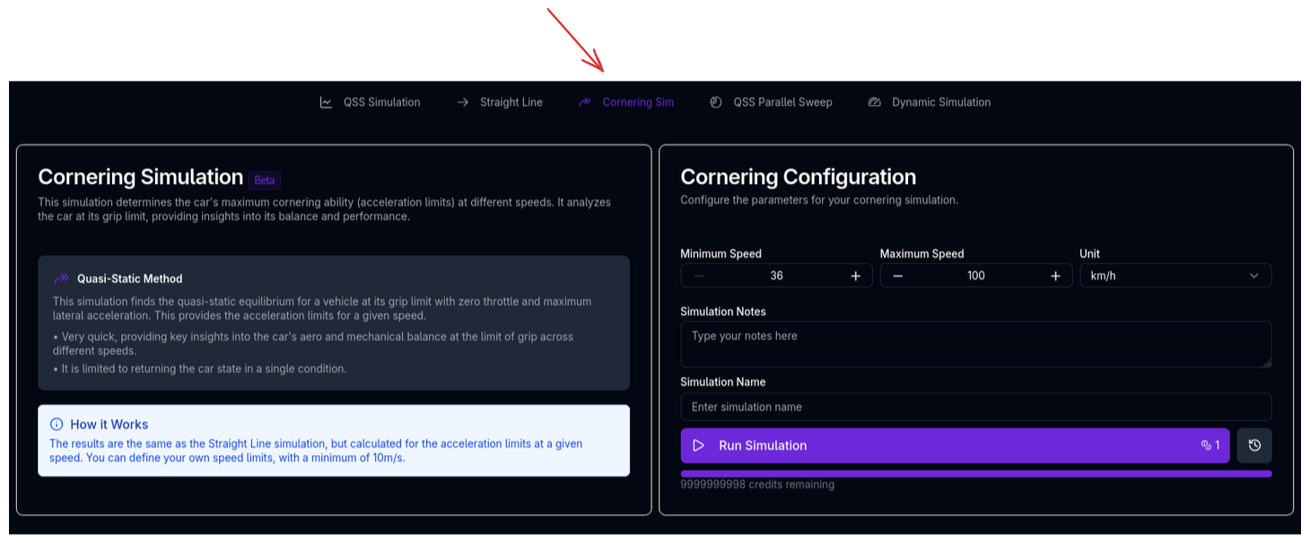
Running the Cornering Simulation
- Ensure your vehicle setup is complete
- Navigate to the Cornering simulation page
- The simulation will use the default speed range
- Enter a Simulation Name and optional notes
- Click Run Simulation
Tips & Best Practices
Compare Aero Configurations
Run the cornering simulation with different aero setups (e.g., high vs low downforce) to see how the lateral g curve changes. The crossover point where one configuration overtakes the other tells you the speed at which the aero trade-off flips.
Read the Yaw Moment
The yaw moment (MYaw) at the cornering limit reveals the vehicle's balance. A positive yaw moment at the limit suggests the car wants to tighten its line (oversteer tendency), while a negative yaw moment suggests it wants to push wide (understeer tendency). This is a more nuanced indicator than simple front vs rear slip angle comparison.
Check Tyre Load Distribution
If one corner consistently shows very low load at the limit, the vehicle may be lifting an inside wheel. This can indicate excessive roll stiffness on that axle or insufficient mechanical grip.
Use for Tyre-Level Insight
When the Lap Time Simulation shows a performance change but doesn't explain why, the cornering simulation provides the tyre-level detail to diagnose the cause — slip angles, individual forces, and yaw moment balance that the QSS approach cannot produce.
Related Topics
- Lap Time Simulation (QSS) — Uses the same cornering physics within the full lap context, but without tyre-level outputs
- Straight Line Simulation — Complementary analysis of the vehicle at zero lateral acceleration
- Handling (YMD) — Yaw moment diagram analysis for detailed balance assessment
- Aerodynamics Setup — Configure the aero model that drives high-speed cornering
- Suspension Setup — Configure springs, dampers, and anti-roll bars that affect load transfer and cornering balance
- Trace View — Visualise cornering simulation results