Initialization
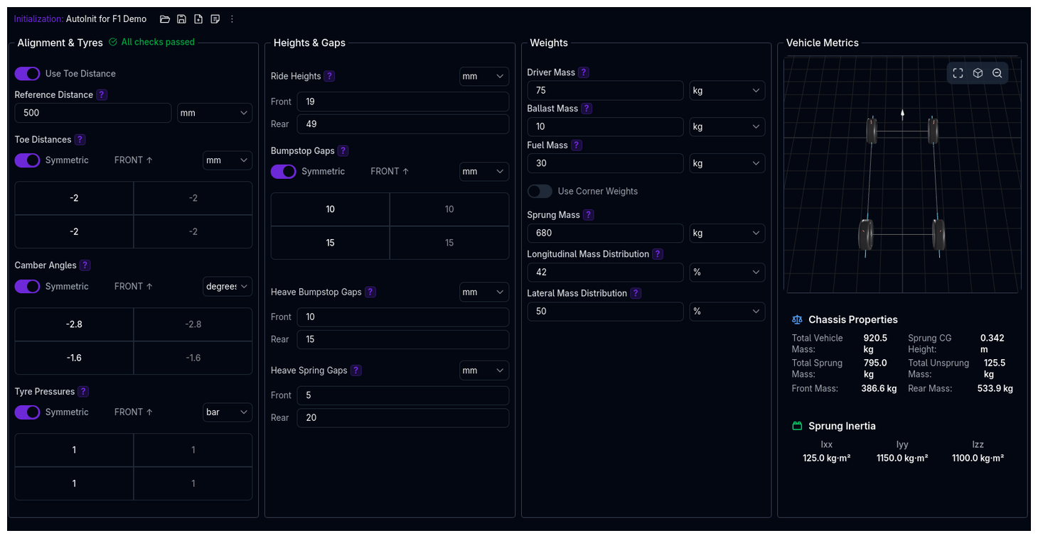 The Initialization page defines the starting state for your vehicle simulations. This is where you set race-ready conditions: ride heights, alignment, tyre pressures, and weight distribution. These parameters establish the baseline from which all simulations begin.
Race-Ready Configuration
The Initialization page defines the actual simulation state of your vehicle (race trim), while the Chassis page defines reference measurements (setup sheet conditions). Changes here affect CG location, load distribution, and kinematics.
Overview
The Initialization setup controls:
- Alignment & Tyres - Toe, camber, and tyre pressures at each corner
- Heights & Gaps - Race ride heights and bumpstop engagement points
- Weights - Driver, fuel, ballast, and corner weight distribution
- Setup Condition - Optional garage state the measurements were taken in
- Vehicle Metrics - Calculated mass properties, static deflections, and inertias (displayed on desktop)
Alignment & Tyres
Toe Configuration
Toe defines the angle between the wheel's heading and the vehicle's centerline. You can specify toe as either an angle or a distance.
Toe Angle (Default)
Enter toe directly in degrees for each corner:
- Positive toe (+): Toe-in (front of wheel points inward)
- Negative toe (-): Toe-out (front of wheel points outward)
Typical values: - Front: -0.1° to +0.3° (slight toe-in for stability) - Rear: 0° to +0.2° (slight toe-in for straight-line stability)
Toe Distance (Alternative)
Enable "Use Toe Distance" to specify toe as a linear measurement (mm) instead of an angle. This matches how many setup sheets and corner weight scales report toe.
Required: Reference Distance
When using toe distance, you must specify the reference distance (typically the wheel rim diameter). This is used to convert the linear toe measurement to an angle.
Conversion Formula:
Example: - Reference distance: 500 mm (rim diameter) - Toe distance: +2 mm (toe-in) - Calculated angle: arctan(2/500) = 0.23°
When to Use Toe Distance
Use toe distance when you have measurements from corner weight scales or setup sheets that report toe in millimeters rather than degrees.
Camber Angles
Camber is the angle between the vertical axis of the wheel and the vertical axis of the vehicle.
- Negative camber (-): Top of wheel tilts inward (most common in motorsport)
- Positive camber (+): Top of wheel tilts outward (rare in racing)
Typical values: - Front: -2.0° to -4.0° (more negative for high downforce/cornering) - Rear: -1.5° to -3.5°
Static vs Dynamic Camber
The camber angles entered here are static (at rest). During cornering, the suspension kinematics will change these angles. See Suspension for camber gain curves.
Tyre Pressures
Set tyre inflation pressures for each corner. These pressures are used throughout the simulation for all calculations.
Typical values: - Road cars: 2.0-2.5 bar (30-36 psi) - Race cars (slicks): 1.4-1.8 bar (20-26 psi) - Formula cars: 1.2-1.6 bar (17-23 psi)
Static Pressure Model
The pressures entered here are used for all tyre calculations including loaded radius and rolling radius. The platform does not model dynamic pressure changes during simulation.
Heights & Gaps
Ride Heights
The race-ready ride height at the front and rear axles. This is the actual ride height used in the simulation.
How it relates to Chassis ride height:
- The Chassis page defines the reference ride height where kinematic pickup points and CG height were measured
- The Initialization ride height defines the race-ready state for simulation
- When initialization ride height differs from chassis reference, the platform automatically:
- Adjusts CG height
- Recalculates inertias
- Updates suspension kinematics
Example: - Chassis reference: Front 50mm, Rear 60mm (setup sheet measurement height) - Initialization: Front 45mm, Rear 55mm (actual race trim, 5mm lower) - Platform adjusts CG and kinematics by the 5mm difference
Typical values: - GT cars: 40-60mm - Formula cars: 20-40mm - Touring cars: 60-80mm
Ride Height Strategy
Lower ride heights reduce CG height (improving handling) but increase risk of bottoming and reduce aerodynamic rake. Find the optimal compromise for your track.
Which reference point to measure from
ARD doesn't mandate a single measurement convention (axle centre, chassis rail, or a ride-height board/"wood" on the ground) — what matters is consistency. Enter ride height here using whatever convention your Aerodynamics maps were generated with, since ride height only affects results correctly if it lines up with the reference the aero platform data was measured against.
Bumpstop Gaps
The free travel at each corner before the bumpstop engages. Measured at static 1g load (nothing engaged at rest).
What they do: - Control when progressive bumpstop springs/dampers activate - Prevent bottoming in high-speed compressions - Fine-tune suspension platform control
Typical values: - 5-15mm (aggressive setup, early engagement) - 15-30mm (balanced setup) - 30-50mm (soft setup, late engagement)
Dependency: Bumpstops Must Be Enabled
Bumpstop gaps are only available if bumpstops are enabled in the Suspension setup. Enable corner bumpstops first.
Heave Bumpstop Gaps
The free travel before the heave bumpstop (third spring damper) engages on the front or rear axle.
What they do: - Control heave (pitch) motion independently from roll - Common in GT cars and Formula cars with third springs - Engage in heave compression (braking/acceleration squat)
Dependency: Heave Bumpstops Required
Available only if heave bumpstops are enabled for that axle in Suspension.
Heave Spring Gaps
The free travel before the heave spring engages.
What they do: - Allow independent heave spring engagement - Commonly used for aerodynamic platform control - Can create bilinear heave stiffness
Dependency: Heave Springs Required
Available only if heave springs are enabled for that axle in Suspension.
Effective Gap at the Wheel
Above the gap fields, a small gauge per corner shows what those numbers actually amount to once load is applied — whether each element still has clearance at the static position, or is already compressed against its stop.
- Green — clearance remains at the static position.
- Red — the element is engaged at rest.
Each gauge is drawn only for the elements you have enabled, so a car with no heave bumpstop simply does not show one. Hover a gauge for the numbers behind it: the running gap, the setup gap where one is defined, and which of the two reasons it is engaged for —
- Entered preloaded — compressed on purpose at the static position.
- Negative gap — the running load has closed the clearance you set at setup.
Both are the same mechanical state, which is why they share a colour; the difference is intent, not behaviour.
Read this before the numbers
A gap that reads as a sensible positive figure in the field above can still be closed once the car is loaded. The gauge is the quickest way to catch that, particularly after a spring, ride height or mass change.
Weights
Driver, Ballast, and Fuel Mass
Enter the mass of:
- Driver: Driver + seat + safety equipment
- Ballast: Additional weight for minimum weight compliance or balance
- Fuel: Fuel load for the simulation
These masses are added to the sprung mass and affect: - Total vehicle mass - CG location (if positions specified in Chassis) - Weight distribution - Inertias (recalculated if positions specified)
Typical values: - Driver: 70-85 kg - Ballast: 0-50 kg - Fuel: 0-100 kg (depends on race length)
Corner Weights vs Mass Distribution
You can specify vehicle weight distribution using two methods:
Method 1: Corner Weights (Recommended for Racing)
Enable "Use Corner Weights" and enter the measured weight at each corner (FL, FR, RL, RR).
When to use: - You have actual corner weight measurements from scales - Most accurate for race applications - Includes driver, fuel, and ballast as measured
Workflow: 1. Place car on corner weight scales 2. Add driver (or equivalent weight), fuel, and ballast 3. Measure each corner's weight 4. Enter directly into ARD
The platform automatically calculates total sprung mass by subtracting unsprung masses (defined in Chassis).
Method 2: Sprung Mass + Distributions (Design/Theoretical)
Enter:
- Sprung Mass: Total mass supported by suspension
- Longitudinal Mass Distribution: Percentage of sprung mass on front axle (%)
- Lateral Mass Distribution: Percentage of sprung mass on left side (%)
When to use: - Design phase (before car is built) - Theoretical studies - No access to corner weight scales
The platform calculates corner weights from these distributions.
Typical distributions: - Longitudinal: 45-50% front (mid-engine), 50-55% front (front-engine) - Lateral: 49-51% left (asymmetric for oval racing), 50% (road racing)
Which Method to Use?
Use corner weights when you have measured data (most accurate). Use mass distributions for design work or when scales aren't available. Both are functionally equivalent.
Setup Condition (Garage State)
Many teams do not set the car up in its race-ready state. Ride heights, gaps, and alignment are often set in the garage with rigid setup wheels (plinths) on the hubs, a setup fuel load, ballast in the seat, and bodywork off. The race-ready values then differ, because the mass, weight distribution, and wheel radius all change between the garage and the track.
The Setup Condition toggle models exactly this. When enabled, the familiar sections become the setup state — marked with a Setup chip — and a compact Running Condition fieldset appears for the race-ready inputs:
- The main sections (Alignment & Tyres, Heights & Gaps, Weights) hold what you set and measure in the garage: ride heights, gaps, toe/camber, the masses on the car while it was measured, and the wheels on the hubs.
- The Running Condition fieldset (blue border) holds the simulation inputs: running driver/ballast/fuel masses and running tyre pressures. There is deliberately no running weight-distribution input — the running distribution is derived by moving each mass delta at its position from the Chassis Movable Masses section (AVL race condition semantics). A mass without a position sits at the CG and shifts nothing.
- The platform computes the running geometry by re-solving the static equilibrium in both states — including nonlinear effects (gap engagement, preloaded springs, tyre radius vs load) and the kinematic toe/camber gain — and shows each computed value in a small blue grid directly under its setup field.
Single Source of Truth
Every quantity appears exactly once: geometry is entered in the setup state and its running value is computed (shown beneath the field and in Vehicle Metrics); masses and pressures exist as separate setup and running inputs because they genuinely are two different quantities.
What happens when you enable it
The Running Condition fields are seeded from your current values, so a freshly enabled Setup Condition changes nothing — the computed running state is identical to what you had. From there, adjust what actually differs between the garage and the track (typically fuel and pressures). Turning the toggle off returns to single-state behaviour with your main values intact.
Positions drive the balance shift
For a running fuel/driver/ballast delta to move the weight distribution, the corresponding position must be set in the Chassis Movable Masses section. Without a position the delta is added at the CG — total mass changes, balance does not. The derived running balance is shown as Front Balance in the Vehicle Metrics panel.
Wheels at setup
With the toggle on, the wheels block in Alignment & Tyres is a strict either/or — never an ambiguous mix:
- Tyres at the setup pressures (default): the main Tyre Pressures field becomes the setup pressure, and the setup loaded radius is computed from the tyre model at the setup loads and these pressures. The running pressures live in the Running Condition fieldset.
- Rigid setup wheels: enter the fixed hub-to-ground radius per corner. Plinths are often machined to match a tyre at a reference pressure.
Camber feeds the tyre model
Besides defining the garage alignment (the running values are computed through the kinematic gain curves), expression-based tyre models also evaluate the setup loaded radius from the setup camber and pressures.
Toe keeps its angle/distance convention: with Use Toe Distance enabled, setup toe is entered as distances using the reference distance and converted to angles on save; the computed running toe is displayed in the same convention.
Reading the results
Every computed running value appears in a small blue grid directly beneath its setup field, mirroring the input layout. The Vehicle Metrics panel adds the axle displacement delta and the setup-state corner weights. Gaps that close completely under the running load show in orange with an engaged at rest tag.
Masses exist in both states — no overlap
With the toggle on, the Weights section and the main Tyre Pressures describe the setup state the car was measured in, while the Running Condition fieldset holds the simulation inputs. Both remain editable — they are genuinely two different quantities, and the measurements change with the mass delta between the states.
Vehicle Metrics (Desktop Only)
On desktop screens (XL breakpoint), a live metrics panel displays calculated vehicle properties:
Static State
- Total Vehicle Mass: Sum of sprung + unsprung + driver + fuel + ballast
- Total Sprung Mass: Mass supported by suspension
- Total Unsprung Mass: Wheels, brakes, hubs, lower suspension components
- Front / Rear Mass: Total weight per axle
- Sprung CG Height: Adjusted for ride height changes and added masses
- Front Balance / Cross Weight: Derived balances of the state the simulation runs from — with a Setup Condition enabled, Front Balance is the read-back for the derived running distribution
Inertias are not displayed
Sprung inertias are deliberately excluded from this panel (and from the underlying endpoint) — they are OEM-sensitive.
Static Deflections
Shown for every car, with or without a Setup Condition:
- Suspension Travel: Static suspension compression from free length, per corner
- Tyre Deflection: Static tyre compression under load, per corner
- Corner Load: Static load at each contact patch (the running loads)
Setup → Running (with Setup Condition enabled)
A self-contained comparison: the axle displacement delta, and both corner weight rows (CW Setup and CW Running) side by side — the running row repeats the Corner Load figure from Static Deflections above, kept here too so the two states can be read off directly without cross-referencing another panel. Everything else — computed ride heights, gaps, toe/camber — lives in small blue grids directly beneath the setup fields; a gap value shown in orange with an engaged at rest tag means the running load closes the clearance set in the garage (simulated correctly, worth verifying it is intentional).
Sprung Inertia
- Ixx: Roll inertia (kg·m²)
- Iyy: Pitch inertia (kg·m²)
- Izz: Yaw inertia (kg·m²)
Live Updates
Metrics update in real-time as you modify parameters, but show a warning if unsaved changes exist. Save your setup to ensure calculations reflect latest edits.
Configuration Workflow
Recommended Workflow
-
Start with a Vehicle Template
- Load a template close to your vehicle type
- Templates include realistic baseline values
-
Set Race-Ready Masses
- Enter driver mass
- Enter fuel load for simulation
- Add ballast if required for minimum weight
-
Configure Ride Heights
- Set front and rear ride heights for race trim
- Platform automatically adjusts CG and kinematics from chassis reference
-
Enter Alignment
- Set camber angles (usually negative for racing)
- Choose toe angle or toe distance method
- Enter toe values per corner
-
Set Tyre Pressures
- Enter cold inflation pressures
- Match your target operating window
-
Define Weight Distribution
- If measured: Enable corner weights, enter scale readings
- If theoretical: Enter sprung mass and distributions
-
Configure Gaps (If Using Bumpstops)
- Enable bumpstops in Suspension first
- Set bumpstop gaps per corner
- Set heave gaps if using third springs
-
Enable the Setup Condition (If You Measure in the Garage)
- Toggle on if your ride heights/gaps/alignment were set on plinths or with a different fuel/driver state than race trim
- All fields seed from your running values — adjust only what differs
- Check the Setup → Running block to confirm the computed race state
-
Review Metrics
- Check calculated mass properties and static deflections (desktop)
- Verify total mass, CG height, weight distribution
- Ensure values are realistic for your vehicle type
Tips & Best Practices
Save Configurations as Setups
Save different initialization setups for different conditions (qualifying vs race, wet vs dry, full fuel vs light). Use the Setup Selector to switch quickly.
Use Tags to Organize
Tag initialization setups by track, fuel load, or condition (e.g., "Spa", "Full-Fuel", "Qualifying") for easy filtering.
Measure, Don't Estimate
For corner weights and alignment, measure whenever possible. Even small errors compound through load transfer calculations and affect simulation accuracy.
Start Conservative with Gaps
When first setting bumpstop gaps, start with larger values (20-30mm). Reduce gaps incrementally to fine-tune platform control without over-constraining suspension.
Monitor Metrics Panel
Watch the Vehicle Metrics panel as you adjust parameters. It instantly shows how changes affect CG height, weight distribution, and inertias.
Bumpstop Gap Dependencies
Gaps only appear when corresponding components are enabled in Suspension. If gap fields are disabled, enable bumpstops/heave springs first.
Reference Distance Matters
When using toe distance, ensure the reference distance matches the actual measurement radius. Using wheel center distance vs rim diameter can introduce 5-10% error in toe angle.
Validation Warnings
The platform validates initialization parameters and displays warnings for:
- Unrealistic alignment values (e.g., camber > 10°, excessive toe)
- Extreme ride heights (too low may cause geometry issues)
- Weight distribution outliers (e.g., >60% front weight)
- Mass inconsistencies (corner weights don't match distributions)
- Gap conflicts (bumpstop gap larger than available suspension travel)
Viewing Warnings
Warnings appear in the Tree View next to the Initialization component. Click the warning icon to view details.
Related Topics
- Chassis Setup - Reference measurements for CG, inertias, and dimensions
- Suspension Setup - Enable bumpstops and heave springs, configure gaps
- Coordinate System - Understanding positive/negative conventions
- Component Hierarchy - How initialization relates to other components
Measurement Resources
Need help measuring these parameters on your actual vehicle? See our Measurement Guide for detailed instructions on:
- Measuring center of gravity height
- Determining anti-roll bar stiffness
- Understanding motion ratios
- Measuring camber and toe
- Calculating suspension kinematics
- And more...