Kinematics
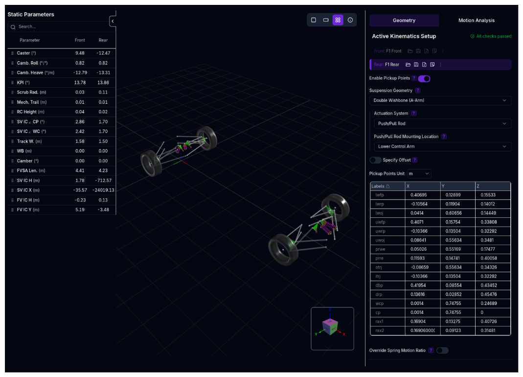 Configure your suspension geometry and analyze how your suspension moves throughout its range of travel. Define pickup points, analyze static parameters, or enter kinematic curves directly.
Overview
The Kinematics setup defines:
- Suspension Type - Double wishbone (push/pull rod or direct acting) or McPherson strut
- Pickup Points - 3D coordinates of suspension mounting points and joints
- Static Parameters - Calculated geometric properties (camber, caster, roll centre height, etc.)
- Kinematic Curves - How suspension geometry changes with wheel travel
- Manual Inputs - Directly entered kinematic parameters vs wheel travel, used when pickup points are not defined
Pickup Points Are the Source of Truth
When pickup points are enabled, they take precedence: the platform calculates all kinematic curves directly from the 3D geometry, and those curves cannot be edited by hand. This keeps the source of your kinematics unambiguous.
To work from values instead of geometry, disable pickup points — every kinematic parameter then becomes directly editable. See Direct Curve Entry.
The exceptions are the heave and ARB motion ratios, which stay editable even with pickup points enabled, whenever the corresponding element is active but has no geometric architecture defined (heave or ARB type set to none). There is no geometry for the platform to derive them from in that case, so you supply them.
Configuration: Pickup Points Mode
Enabling Pickup Points
- Navigate to Geometry tab
- Toggle Enable Pickup Points switch
Start From the Computed Geometry
With pickup points enabled, a Copy curves & Disable button sits next to the switch. It copies the currently computed curves for that corner — camber, toe, caster, KPI, roll centre height, side-view instant centre angles, wheelbase and track migration, and motion ratios — into the manual curve fields, then turns pickup points off so you can hand-tune from there. Nothing is written until you save.
Recommendation
Run a standalone kinematic analysis first to verify geometry is correct before using pickup points in: - Lap Time Simulation - Ride Analysis - Handling Analysis - Calculations
Selecting Suspension Type
Use the Suspension Type dropdown to choose the suspension family first, then the wheel-side mounting point.
Double wishbone push/pull rod
- Lower Control Arm
- Upper Control Arm
- Upright
Double wishbone direct acting
- Lower Control Arm
- Upper Control Arm
- Upright
McPherson strut
- Upright
Mounting Point Explanation
- LCA: Pushrod/spring attaches to lower wishbone
- UCA: Pushrod/spring attaches to upper wishbone
- Upright: Pushrod/spring attaches directly to wheel carrier
Defining Pickup Points
Step 1: Set Coordinate Unit
Choose the unit for pickup point coordinates: - Millimeters (mm) - default - Meters (m) - Inches (in)
Step 2: Enter Pickup Points
The spreadsheet shows required pickup points for your suspension type. Enter X, Y, Z coordinates for each point.
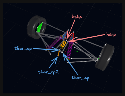
For T-bar heave systems, the pickup point list includes:
- hsrp — heave spring rocker pickup
- hsbp — heave spring body point
- tbar_ap — T-bar arm end point
- tbar_cp and tbar_cp2 — the two centre points that define the T-bar pivot axis
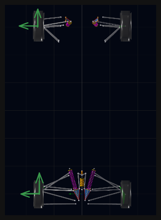
Coordinate System: - Origin: Center of front axle at ground level - X-axis: Positive toward front (longitudinal) - Y-axis: Positive toward left (lateral) - Z-axis: Positive upward (vertical)
See Coordinate System for details.
Example (Double Wishbone):
| Label | X (mm) | Y (mm) | Z (mm) |
|---|---|---|---|
| Lower Wishbone Front Pivot (lwfp) | 207 | 19 | 222 |
| Lower Wishbone Rear Pivot (lwrp) | -347 | 193 | 247 |
| Lower Wishbone Outer Joint (lwoj) | -13 | 712 | 175 |
| Upper Wishbone Front Pivot (uwfp) | 48 | 155 | 412 |
| Upper Wishbone Rear Pivot (uwrp) | -342 | 191 | 428 |
| Upper Wishbone Outer Joint (uwoj) | -42 | 670 | 349 |
Step 3: Optional Offset
Apply a global offset to all pickup points using Offset coordinates. Useful for: - Adjusting suspension position without re-entering all points - Testing sensitivity to pickup point location
Pickup Point Reference
Pickup point names are short because they are used in spreadsheets, imports, exports, and solver data. The tables below map each short key to the physical point you should measure.
Measuring Left and Right Sides
Enter points using the vehicle coordinate system shown above. For symmetric suspensions, the left and right sides should usually be mirrored in Y, while X and Z stay comparable. Centreline points such as some T-bar and heave spring points may sit on or near Y = 0.
Common Wheel and Steering Points
These points appear in most suspension types.
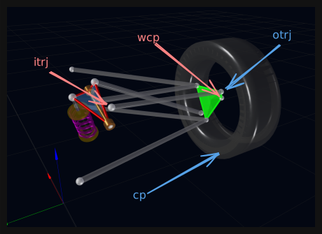
| Key | Point | What to measure |
|---|---|---|
wcp |
Wheel centre point | The centre of the wheel/hub. This is the reference for wheel travel, steering axis measurements, and wheel-centre side-view IC angles. |
cp |
Contact patch | The tyre contact point on the ground plane, usually vertically below the wheel centre at static ride height. |
itrj |
Inner track rod ball joint | The inboard steering rack or steering link joint on the chassis side. |
otrj |
Outer track rod ball joint | The outboard steering link joint on the upright. This controls toe and bump steer. |
Double Wishbone Chassis and Upright Points
These points define the upper and lower wishbone geometry.
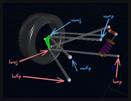
| Key | Point | What to measure |
|---|---|---|
lwfp |
Lower wishbone front chassis mount | Front inboard pivot of the lower wishbone on the chassis. |
lwrp |
Lower wishbone rear chassis mount | Rear inboard pivot of the lower wishbone on the chassis. |
lwoj |
Lower wishbone outer upright mount | Outboard lower ball joint or spherical bearing on the upright. |
uwfp |
Upper wishbone front chassis mount | Front inboard pivot of the upper wishbone on the chassis. |
uwrp |
Upper wishbone rear chassis mount | Rear inboard pivot of the upper wishbone on the chassis. |
uwoj |
Upper wishbone outer upright mount | Outboard upper ball joint or spherical bearing on the upright. |
The line from lwoj to uwoj is the steering/kingpin axis for double wishbone kinematics. It is used for caster, KPI, scrub radius, mechanical trail, and instant-centre extraction.
Push/Pull Rod and Rocker Points
These points are required for double wishbone suspensions with rocker actuation.
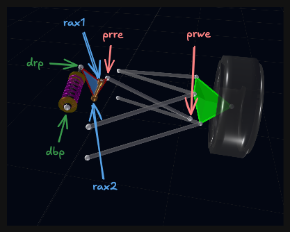
| Key | Point | What to measure |
|---|---|---|
prwe |
Push rod wishbone end | Outboard end of the push rod or pull rod. Depending on the mounting option, this may be on the lower wishbone, upper wishbone, or upright. |
prre |
Push rod rocker end | Inboard end of the push rod or pull rod where it attaches to the rocker. |
rax1 |
Rocker axis 1st point | First point on the rocker pivot axis. |
rax2 |
Rocker axis 2nd point | Second point on the rocker pivot axis. Together with rax1, this defines the rocker rotation axis. |
drp |
Damper to rocker point | Damper, spring, or bellcrank point on the rocker. |
dbp |
Damper to body point | Fixed damper or spring mount on the chassis/body side. |
The rocker axis is defined by rax1 and rax2. The solver rotates rocker-mounted points around this axis, so these two points should describe the real bearing or shaft axis rather than a visual centre of the rocker body.
Heave Spring and T-Bar Points
These points appear when a heave system is enabled.
| Key | Point | What to measure |
|---|---|---|
hsrp |
Heave spring rocker point | Heave spring pickup on the rocker. For a cross-car heave rod, this is the per-side rocker point used to calculate cross-car heave spring movement. |
hsbp |
Heave spring body point | Fixed body-side heave spring point. For T-bar systems this is an axle-level point, often on or near the vehicle centreline. |
tbar_ap |
T-bar arm end point | End of the T-bar arm connected to the rocker-side linkage. |
tbar_cp |
T-bar centre point | First point on the T-bar pivot axis. |
tbar_cp2 |
T-bar second centre point | Second point on the T-bar pivot axis. Together with tbar_cp, this defines the T-bar rotation axis. |
For T-bar heave systems, tbar_cp and tbar_cp2 define the pivot axis, while tbar_ap defines the lever arm. The heave spring movement is calculated from the T-bar spring point to hsbp.
Can't find or measure tbar_cp2 on the real car
On a narrow T-bar mount, tbar_cp and tbar_cp2 can sit close enough together that there is no separate physical point to measure for the second one. In that case it is enough to measure tbar_cp and offset tbar_cp2 from it by a few millimetres along the Z-axis — this only needs to define the rotation axis direction, not mark a second real-world hardpoint.
U-Bar ARB Points
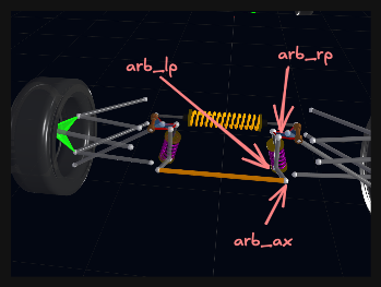
These points appear when the ARB type is set to U-Bar.
| Key | Point | What to measure |
|---|---|---|
arb_ax |
ARB torsion tube axis | Per-side bearing point on the ARB torsion tube axis. The left and right arb_ax points define the cross-car tube axis. |
arb_lp |
ARB lever point | End of the ARB lever arm. |
arb_rp |
ARB rocker point | Rocker-side ARB pickup point. |
The U-bar ARB calculation uses these points to solve ARB twist, lever displacement, and ARB motion ratio. If the ARB hardware is not represented by a U-bar linkage, use manual ARB motion-ratio data instead.
Direct Acting Double Wishbone Point
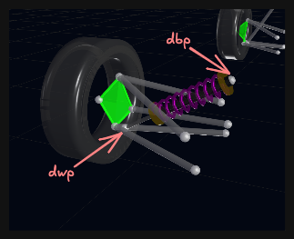
Direct acting double wishbone suspensions use the normal wishbone, steering, wheel centre, and contact patch points, plus one damper/spring wheel-side point.
| Key | Point | What to measure |
|---|---|---|
dwp |
Damper wishbone point | Wheel-side damper/spring attachment point. Depending on the mounting option, this may be on the lower wishbone, upper wishbone, or upright. |
The fixed chassis-side damper point is still dbp.
McPherson Strut Points
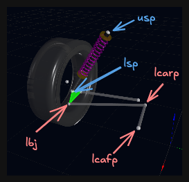
McPherson strut suspensions replace the upper wishbone with a strut axis.
| Key | Point | What to measure |
|---|---|---|
lcafp |
Lower control arm front pivot | Front inboard pivot of the lower control arm on the chassis. |
lcarp |
Lower control arm rear pivot | Rear inboard pivot of the lower control arm on the chassis. |
lbj |
Lower ball joint | Outboard lower ball joint on the upright/knuckle. |
lsp |
Lower strut point | Lower strut attachment point on the upright/knuckle. |
usp |
Upper strut point | Upper strut mount on the chassis/body. |
For McPherson kinematics, the steering/kingpin axis is defined by the lower ball joint and upper strut point.
Suspension Types
Double Wishbone Push/Pull Rod
The most common race car suspension. Uses upper and lower wishbones (A-arms) with a push rod or pull rod actuating a rocker and spring/damper.
Configuration options:
| Option | Choices | Notes |
|---|---|---|
| Mounting point | Lower Control Arm (LCA), Upper Control Arm (UCA), Upright | Defines where the pushrod or pullrod attaches on the wheel side. |
| ARB type | None, U-Bar, T-Bar | U-Bar requires ARB axis and lever pickup points so the solver can calculate twist, lever displacement, and motion ratio. T-Bar uses the T-bar torsion element and is independent of the heave type — it can be paired with a cross-car heave spring or with none. |
| Heave type | None, Cross (rod), T-Bar | Adds the matching heave pickup points automatically. |
Use when: - Formula cars, prototypes, high-performance sports cars - Maximum adjustability and tunability required - Advanced setup with rocker and motion ratio adjustment
Required pickup points:
- Wheel and steering:
wcp,cp,itrj,otrj - Lower wishbone:
lwfp,lwrp,lwoj - Upper wishbone:
uwfp,uwrp,uwoj - Push/pull rod:
prwe,prre - Rocker and damper:
rax1,rax2,drp,dbp - Cross heave spring:
hsrp— orchrpwhen a T-Bar ARB is also fitted, since the T-bar takeshsrpover as its drop link - T-Bar heave system or T-Bar ARB:
hsrp,hsbp,tbar_ap,tbar_cp,tbar_cp2 - U-Bar ARB:
arb_ax,arb_lp,arb_rp
3rd Spring (Heave Spring) - BETA
The 3rd spring option adds additional pickup points for a heave spring connected to the rocker. This feature requires heave spring to be enabled in Suspension settings. This is commonly used in Formula cars and prototypes to control pitch and heave independently from roll.
Double Wishbone Direct Acting
Double wishbone with spring/damper mounted directly between chassis and wishbone (no rocker).
Configuration options:
| Option | Choices | Notes |
|---|---|---|
| Mounting point | Lower Control Arm (LCA), Upper Control Arm (UCA), Upright | Defines where the damper/spring attaches on the wheel side. |
Use when: - Simpler suspension without rockers - GT cars, touring cars, road cars - Space constraints prevent rocker installation
Required pickup points:
- Wheel and steering:
wcp,cp,itrj,otrj - Lower wishbone:
lwfp,lwrp,lwoj - Upper wishbone:
uwfp,uwrp,uwoj - Damper/spring:
dwp,dbp
Direct acting suspensions do not use rocker points (prre, rax1, rax2) or a pushrod wheel-end point (prwe).
Torsion Bar Incompatibility
Direct acting suspension cannot be used with torsion bar springs. If torsion bar is enabled on an axle, direct acting options are disabled.
McPherson Strut
Simplified suspension using a strut (combined spring/damper) acting as the upper suspension member.
Use when: - Front-wheel drive cars, compact vehicles - Packaging constraints require compact suspension - Simpler suspension geometry acceptable
Required pickup points:
- Wheel and steering:
wcp,cp,itrj,otrj - Lower control arm:
lcafp,lcarp,lbj - Strut:
usp,lsp
Steering
Front corners carry a Steering section that sets how driver steering-wheel input reaches the road wheels. Which field you get depends on whether the corner has pickup points defined:
| Field | When it applies | What it means |
|---|---|---|
| Rack Ratio | Pickup points defined | Steering-wheel angle per unit of rack travel (rad/m or deg/mm). A live readout shows the resulting rack travel per turn and the turns lock-to-lock |
| Steering Ratio | No pickup points | A single overall ratio from steering wheel to road wheel, used when there is no rack geometry to derive one from |
This makes the simulated steering trace directly comparable with a logged one. Three channel groups report it:
| Channel | Description |
|---|---|
| aSteerWheel | Driver steering-wheel angle |
| xSteerRack | Steering rack displacement |
| aWheelFL … aWheelRR | Each corner's actual road-wheel angle, combining steer and toe |
Toe channels exclude steer
The existing toe-angle channels report toe only. Use the wheel-angle channels above when you want the total road-wheel angle including steering input.
Static Parameters
The left panel shows calculated static parameters in real-time:
Alignment: - Camber - Wheel tilt (negative = top tilted in) - Caster - Steering axis angle in side view - Toe - Wheel pointing angle (positive = toe out)
Geometry: - Kingpin Inclination (KPI) - Steering axis angle in front view - Scrub Radius - Offset of KPI axis from contact patch - Mechanical Trail - Caster offset at ground
Roll Centre: - Roll Centre Height - Virtual pivot point for body roll - Side View IC Angle (CP) - Contact-patch side-view IC angle used for braking anti calculations - Side View IC Angle (WC) - Wheel-centre side-view IC angle used for drive anti calculations - Anti-dive / Anti-lift / Anti-squat - Longitudinal load-transfer geometry derived from the side-view instant centre, depending on axle and acceleration/braking direction
Instant Centre: - Front View IC Height - Front view instant centre height - Front View IC Y - Front view instant centre lateral position - Side View IC Height - Side view instant centre height - Side View IC X - Side view instant centre longitudinal position
Other: - Track Width - Distance between contact patches - Wheelbase - Distance to opposite axle - Front View Swing Arm Length (FVSA) - Virtual swing arm length - Wheelbase Migration - Wheelbase change with travel - Track Migration - Track width change with travel
Reordering Parameters
Drag parameters (using the grip icon) to reorder them in the table. Your custom order is saved.
Interactive 3D Viewer
The Kinematics page features a fully interactive 3D suspension viewer that animates in real time, rendering wheels with realistic tyre profiles — sidewall, shoulder, and rim proportions — for a clearer picture of how the suspension geometry relates to the tyre contact patch.
Motion Sliders
Three sliders below the 3D viewer let you drive the suspension through its range of travel:
- Heave (mm) — Vertical displacement of the chassis
- Roll (°) — Body roll angle
- Steer (mm) — Rack displacement (front axle only, when steering geometry is defined)
Dragging any slider animates all pickup points to their interpolated positions in real time. Each slider has a Play/Pause button that auto-animates the full range. Only one motion mode can be active at a time.
Overlay Markers
Toggle buttons below the sliders control three overlay markers that update continuously:
- RC — Roll axis line connecting front and rear roll centres
- IC — Instant centre markers for all four corners (FL, FR, RL, RR)
- CG — Sprung centre of gravity sphere
Camera Presets
The viewer toolbar includes one-click camera presets:
| Preset | View |
|---|---|
| ISO | Isometric |
| TOP | Plan (bird's eye) |
| FRT | Front view |
| SDE | Side view |
An Orthographic toggle switches between perspective and orthographic projection.
Use the buttons, not the keyboard
These views no longer have single-key shortcuts — typing a name containing R, T, F, or S into a dialog was moving the camera behind it. Arrow keys still rotate the view.
Sparkline Sidebar
The left-hand parameter sidebar shows a compact sparkline curve for each channel, with a white dot tracking your current slider position. Values update instantly as you drag. Parameters are draggable for reordering and include a search filter.
Motion Analysis
Purpose
The Motion Analysis runs three concurrent sweeps per axle — heave, roll, and steer — and delivers results as a single precompute payload.
Live Precompute
A background precompute job fires automatically when you open the Kinematics page. Once complete, the Current toggle in the Analysis tab plots the live data directly — no need to run and stage a simulation first. Staged simulation results can be overlaid on top.
Sweep Mode
A sweep mode selector (Heave / Roll / Steer) controls which motion axis appears on the x-axis of all charts, with axis labels updating accordingly (Wheel Displacement mm, Roll Angle °, or Rack Displacement mm).
Configuration
Heave Limits: - Min/max wheel displacement for the heave sweep
Rack Limits: - Min/max rack displacement for the steer sweep (when steering geometry is defined)
Available Channels
Motion Ratios: - Spring Motion Ratio - Damper Motion Ratio - Heave Spring Motion Ratio (if applicable, shared by heave spring and damper)
Alignment: - Camber - Toe - Caster - King Pin Inclination
Roll Centre: - Roll Centre Height - Side View IC Angle (Contact Patch) - Side View IC Angle (Wheel Centre)
Instant Centre: - Front View IC Height - Front View IC Y Position - Side View IC Height - Side View IC X Position
ARB: - ARB Twist Angle (aArbTwistF, aArbTwistR) - ARB Lever Displacement - ARB Motion Ratio (maArbF, maArbR)
Anti-Geometry: - Anti-Dive — percentage of front braking load transfer resisted by geometry - Anti-Lift — equivalent metric under rear braking - Anti-Squat — percentage of rear drive thrust load transfer resisted by geometry
Steer: - Ackermann Percentage — computed across the full rack travel range
Migration: - Halftrack Migration (per corner) - Wheelbase Migration (per corner)
Other: - Rocker Angle (if applicable) - Mechanical Trail - Scrub Radius - Front View Swing Arm Length
Comparing Results
Use Simulation Viewer Table to: - Load previous kinematic analyses - Compare different suspension geometries - Overlay curves from multiple runs
Configuration: Direct Curve Entry
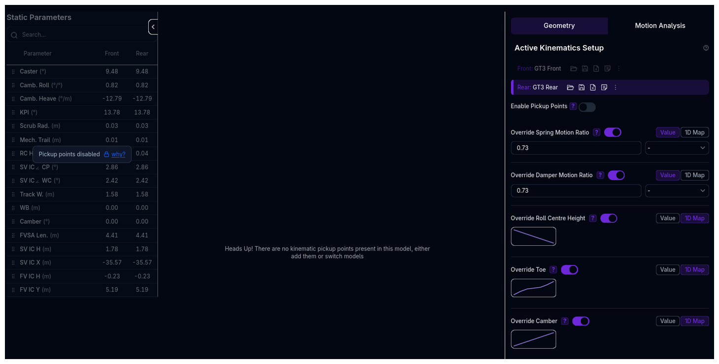
With pickup points disabled, you enter the kinematic curves directly instead of deriving them from geometry. Every parameter below becomes editable, which is the approach to use when your curves come from testing, from a measuring rig, or from another simulation package rather than from a CAD model.
Available Parameters
Each parameter can be configured as: - Numeric - Fixed value (no variation with wheel travel) - Map1D - Curve defined vs wheel travel
Motion Ratios
Spring Motion Ratio: - Ratio of spring displacement to wheel displacement - Higher ratio = stiffer effective wheel rate for the same spring - Typical range: 0.5 - 2.0
Damper Motion Ratio: - Ratio of damper displacement to wheel displacement - Usually similar to spring motion ratio - Typical range: 0.5 - 2.0
Heave Spring Motion Ratio: - Motion ratio for the heave spring and damper (if enabled) - Only shown if a heave element is active. The heave spring and damper share this single motion ratio.
Torsion Bar vs Coilover
For torsion bar suspensions, spring motion ratio is in rad/m instead of m/m (angular displacement per wheel travel).
Alignment Parameters
Roll Centre Height: - Height of roll centre above ground - Affects lateral load transfer distribution - Typical range: -50mm to 500mm - Negative = below ground
Toe: - Toe angle change vs wheel travel - Positive = toe out, negative = toe in - Can cause bump steer if excessive
Camber: - Camber angle change vs wheel travel - Negative = top of wheel tilted in - Camber gain in bump improves cornering grip
Caster: - Caster angle change vs wheel travel - Positive = top of kingpin behind bottom - Usually relatively constant through travel
Instant Centre Angles
IC Angle (Contact Patch): - Side view instant centre angle from contact patch - Used for braking anti calculations: front anti-dive and rear anti-lift - Positive = IC above the contact patch reference
IC Angle (Wheel Centre): - Side view instant centre angle from wheel centre - Used for drive anti calculations: front anti-lift and rear anti-squat
King Pin Inclination: - Front view steering axis angle - Affects steering feel and self-centering
ARB Motion Ratio
ARB Motion Ratio:
- ARB twist angle per unit of sprung roll angle (rad/rad), not displacement per unit wheel travel
- Can be entered as a constant value or as a 1D curve vs. roll angle for non-linear installations
- Not comparable to the spring or damper motion ratio; values of 5-15 rad/rad are normal
- Only editable when ARB type is none — with U-bar or T-bar geometry it is solved from the pickup points
- See Anti-Roll Bars for how it is solved and how it feeds roll stiffness
ARB Type:
- Architectural style of the anti-roll bar: none, u_bar, or tbar. The T-bar ARB is independent of the heave system: it can be fitted alongside a T-bar heave spring, a cross-car heave spring, or no heave spring at all. Pairing it with a cross-car spring needs a chrp pickup point, because hsrp then carries the T-bar drop link.
Heave Type: - Architectural style of the heave system (e.g., push/pull-rod heave)
Rack Limits: - Configurable steering rack travel limits
Heave Limits: - Configurable heave travel limits
ARB Motion Ratio
The ARB motion ratio lives in the Kinematics component, where it belongs geometrically. Define your ARB motion ratio here. The bar's stiffness and damping stay on the Anti-Roll Bars page.
Migration Parameters
Wheelbase Migration: - Change in wheelbase with wheel travel - Can affect pitch behavior
Track Migration: - Change in track width with wheel travel - Affects scrub and cornering geometry
Rocker Angle: - Rocker rotation angle vs wheel travel - Only relevant for rocker suspensions
Entering Parameter Values
For each parameter:
1. Choose Data Type
- Numeric: Enter single value
- Map1D: Define curve vs wheel travel
2. For Map1D: Define Curve
- X-axis: Wheel Travel (m)
- Negative = rebound (extension)
- Positive = bump (compression)
- Y-axis: Parameter value
- Define multiple points, platform interpolates
Example: Camber Curve
| Wheel Travel (mm) | Camber (°) |
|---|---|
| -30 | -1.5 |
| -20 | -1.8 |
| -10 | -2.0 |
| 0 | -2.2 |
| 10 | -2.3 |
| 20 | -2.5 |
| 30 | -2.6 |
This defines camber gain: wheel gains negative camber (good for cornering) as it compresses.
Kinematics View Layout
The Kinematics page has two tabs:
1. Geometry Tab
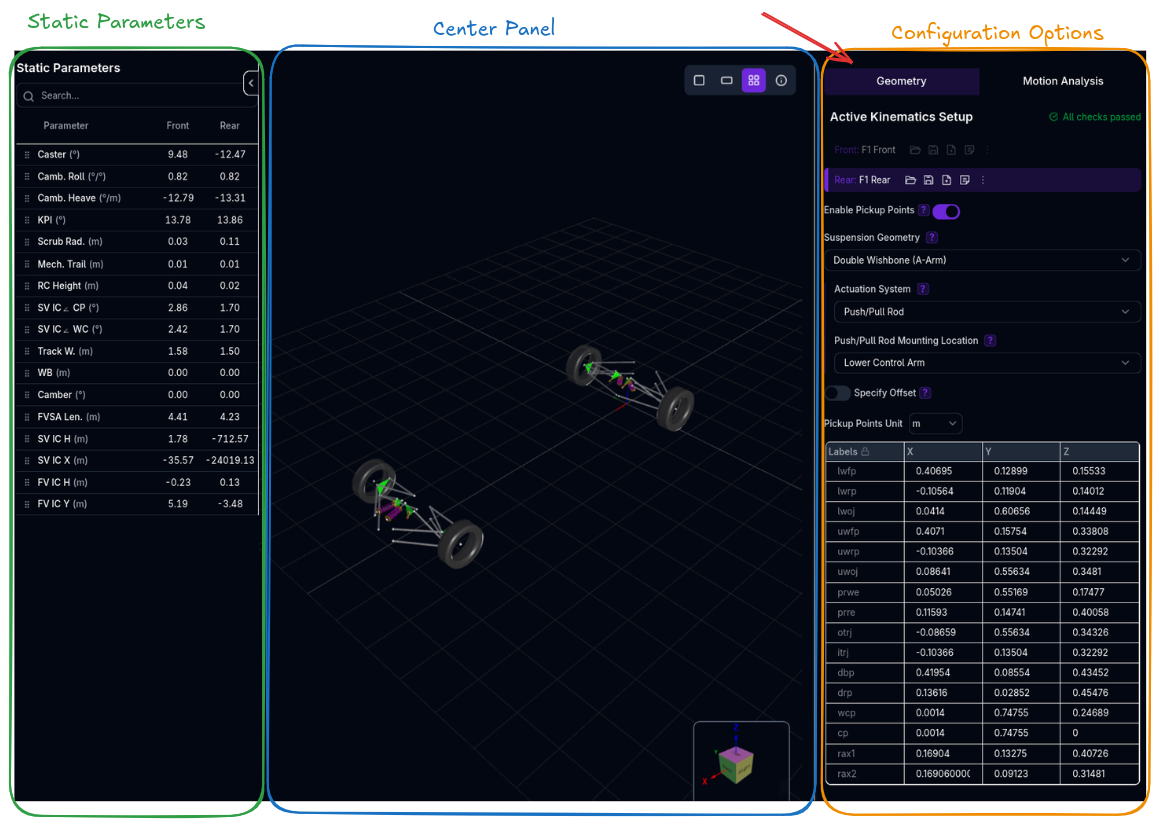
Left Panel (Collapsible): - Static Parameters Table - Real-time calculated geometric properties - Search and reorder parameters
Center Panel: - 3D Suspension Visualizer - Interactive view of suspension geometry - Shows pickup points, links, and current wheel position - Updates in real-time as you edit
Right Panel: - Configuration Options - Suspension type, pickup points, kinematic parameters
2. Motion Analysis Tab
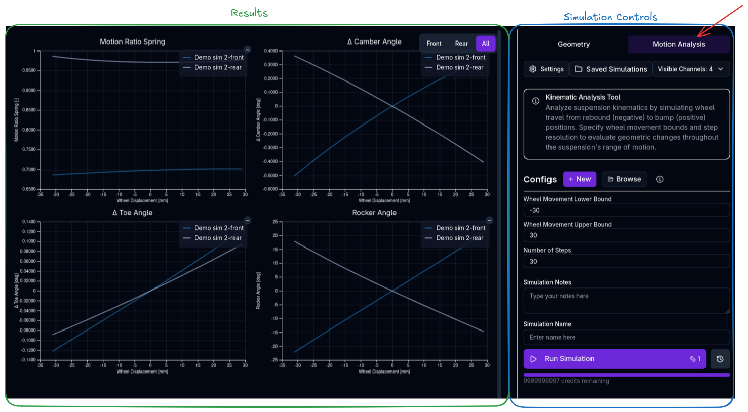
Center Panel: - Kinematic Curves - Plots of all kinematic parameters vs wheel travel
Right Panel: - Simulation Controls - Configure and run kinematic analysis - Wheel travel range and step resolution
Understanding Kinematics
What is Suspension Kinematics?
Suspension kinematics describes how suspension geometry changes as the wheel moves through its travel. As the suspension compresses (bump) or extends (rebound), the geometric relationships between suspension components change, affecting:
- Camber angle - Wheel tilt relative to vertical
- Toe angle - Wheel pointing in/out
- Motion ratios - Mechanical leverage between wheel and spring/damper
Why It Matters
Suspension kinematics directly impacts:
- Tyre contact patch - Camber and toe changes affect grip
- Mechanical grip - Roll centre location affects load transfer
- Ride quality - Motion ratios affect suspension response
- Handling balance - Kinematic curves differ front vs rear
How the Platform Calculates Kinematic Outputs
This section explains the calculation conventions used by the platform. It is intended to help you interpret the values shown in the setup page and understand how they feed the rest of the vehicle model.
Units and Sign Conventions
- Distances are stored and calculated in metres. The interface may display mm for readability.
- Angles are stored and calculated in radians. The interface may display degrees.
- Wheel movement is compression-positive in user-facing curves: positive wheel travel means bump/compression, negative wheel travel means rebound/extension.
- Kinematic curves are normally zero-referenced to the static geometry used for the analysis. For example, camber and toe curves describe the change from the static value, while Initialization provides the race-ready static camber and toe baseline used by simulations.
Solved Geometry and Instant Centres
When pickup points are enabled, the solver first finds a valid 3D position for all constrained suspension points at each requested wheel travel, roll, or steer position. It then extracts the engineering quantities from those solved positions.
Instant centres are calculated with a small movement perturbation rather than only by drawing wishbone lines. At each point in the sweep, the solver moves the mechanism by a very small heave step and calculates the velocity of two upright points. The instant centre is the intersection of the lines perpendicular to those velocity vectors.
This is important because it captures the actual motion of the solved mechanism, including bump-steer coupling and non-wishbone topologies such as McPherson struts. If the lines are nearly parallel, the instant centre becomes very far away; the platform handles this numerically rather than treating the suspension as invalid.
Roll Centre
The front-view instant centre is projected into the front-view plane. The roll centre height is then found by drawing a line from the contact patch to that instant centre and intersecting it with the vehicle centreline.
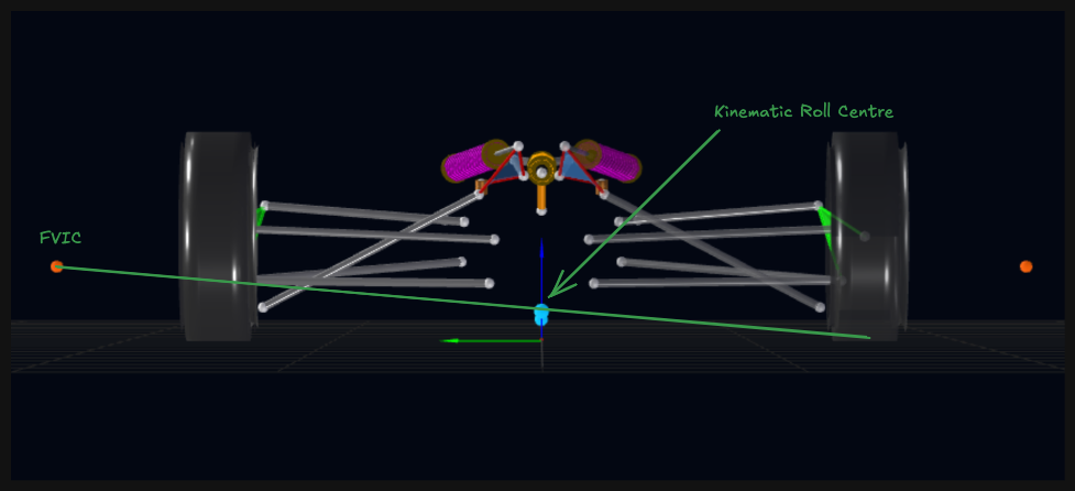
Roll centre height is reported relative to the road/contact-patch level:
A positive value is above the road surface. A negative value is below the road surface.
Side-View IC Angles
The platform reports two side-view instant-centre angles:
- IC Angle (Contact Patch): angle from the contact patch to the side-view instant centre
- IC Angle (Wheel Centre): angle from the wheel centre to the side-view instant centre
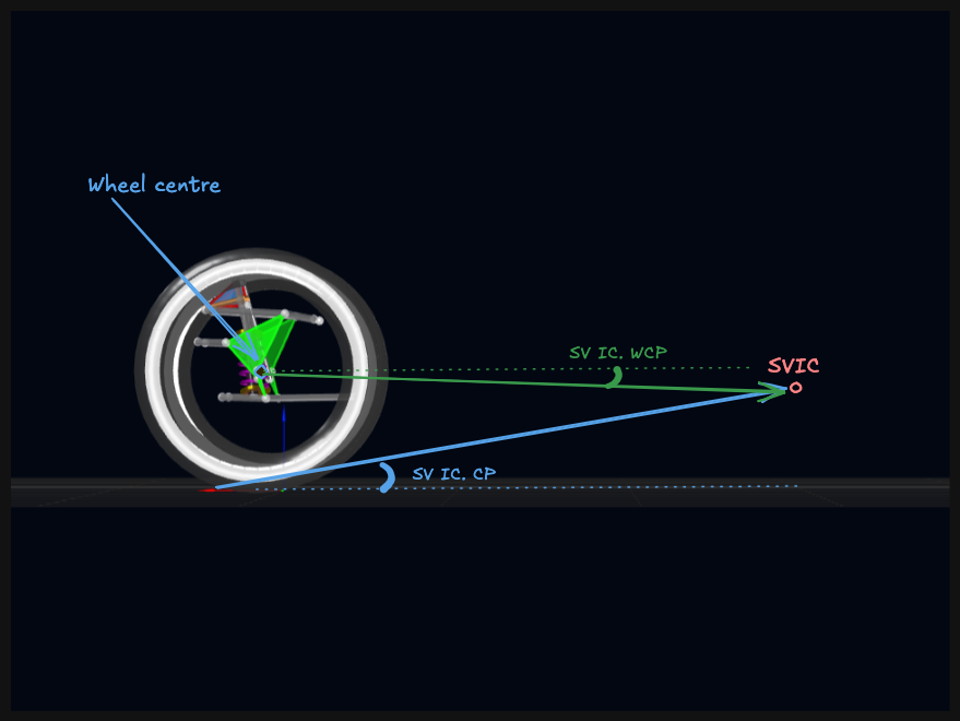
The sign convention is:
Because the denominator uses the absolute longitudinal distance, a positive angle means the instant centre is above the reference point, whether it is ahead of or behind that point. A negative angle means the instant centre is below the reference point.
Anti-Dive, Anti-Lift, and Anti-Squat
Anti behaviours are calculated from the side-view IC angles, current wheelbase, current sprung centre-of-gravity height, brake bias, and powertrain torque distribution. They are returned as ratios. For example, 0.30 means 30%.
The formulas are:
anti-dive       = brake bias * tan(front IC angle from CP) * wheelbase / CG height
rear anti-lift  = (1 - brake bias) * tan(rear IC angle from CP) * wheelbase / CG height
front anti-lift = front torque distribution * tan(front IC angle from WCP) * wheelbase / CG height
anti-squat      = rear torque distribution * tan(rear IC angle from WCP) * wheelbase / CG height
Where:
- Brake bias is the current front brake bias from the brake system at the evaluated speed.
- Front torque distribution is the fraction of drive torque sent to the front axle.
- Rear torque distribution is
1 - front torque distribution. - Wheelbase includes wheelbase migration from the current front and rear wheel movements.
- CG height includes the current ride-height and pitch state.
The values are not clipped to 0-100%. Negative values and values above 100% can be physically meaningful. A negative value means the geometry creates a pro-effect rather than an anti-effect. Values above 100% mean the geometry effect exceeds the simple load-transfer reference used by the formula.
Near-Vertical Side-View IC
If the side-view instant centre sits almost directly above the contact patch or wheel centre, tan(angle) approaches infinity. In that degenerate case the platform returns 0 for the affected anti value rather than reporting an unstable infinite value.
Brake Force Assumption
ARD currently assumes outboard wheel brakes, where braking force is reacted at the tyre contact patch. Inboard brakes mounted on the chassis or differential are not currently modelled, so rear anti-lift uses the contact-patch side-view IC angle.
Motion Ratios
Spring and damper motion ratios are calculated as movement of the inboard element divided by wheel movement:
spring motion ratio = spring movement / wheel movement
damper motion ratio = damper movement / wheel movement
For coilover-style springs this is dimensionless. For torsion bars, the spring motion ratio is angular movement per wheel movement, so its unit is rad/m.
Motion Ratio Convention
Some external tools define coilover motion ratio as wheel movement / spring movement. ARD uses the inverse convention: spring or damper movement / wheel movement. If you are copying values from another tool, confirm the convention before entering the curve.
In a heave sweep, the platform uses the zero-referenced movement across the sweep to calculate the reported motion-ratio curve. This avoids local numerical spikes near singular points and matches the value expected by spring and damper rate calculations. In roll or steer sweeps, spring and damper motion ratios are suppressed because wheel movement is near zero and the ratio is not meaningful.
ARB and Heave Motion Ratios
ARB motion ratio is handled as a roll-based quantity:
It is queried against sprung roll, not wheel travel. This allows roll-dependent ARB installations to change effective ARB rate with roll angle. The value reported is the local derivative of the solved twist-vs-roll curve, so a non-linear installation correctly reports a motion ratio that varies with roll.
For a U-bar the twist is the full relative twist across the torsion tube — both arms' rotations against the centre — which must match how the bar's stiffness was measured. See Anti-Roll Bars for the full derivation and a hand check.
The heave spring motion ratio is only present when a heave element is configured. For a cross-car heave rod, the platform calculates the change in length between the left and right heave spring rocker points. For a T-bar heave system, it calculates the change in length from the T-bar spring point to the body point. The reported heave spring motion ratio is that heave spring movement divided by wheel movement.
Migration Values
Wheelbase and track migration come from contact patch movement:
wheelbase migration = -(current contact patch X - initial contact patch X)
half-track migration = current contact patch Y - initial contact patch Y
The complete car model uses these values as follows:
current wheelbase = reference wheelbase - front wheelbase migration + rear wheelbase migration
current front track = reference front track + front half-track migration total
current rear track  = reference rear track + rear half-track migration total
When 2D heave-by-roll maps are available, axle-level roll centre, wheelbase migration, and track migration are calculated from the left and right corner maps. Roll centre and wheelbase migration use the left/right average. Track migration uses the combined left/right half-track change.
Reference Ride Height Adjustment
Chassis defines the reference ride heights where the pickup points were measured. Initialization defines the race-ready ride heights used for the current setup. If these differ, the platform shifts kinematic lookups by:
For most kinematic fields, a query at wheel movement x reads the curve at x + reference delta. Camber and toe are then re-zeroed at the race-ready static position so they still behave as changes relative to the initialization camber and toe.
For pushrod/rocker-actuated axles, inboard reference-position fields stay tied to the measured reference geometry. This applies to spring motion ratio, damper motion ratio, heave spring motion ratio, and rocker angle. This reflects the pushrod-length interpretation of a reference ride-height change rather than moving every inboard curve with wheel travel.
Validation Warnings
The platform validates suspension geometry and warns for:
Link Length Warnings: - Link length <5mm (suspiciously short) - Links should be >5mm for realistic geometry
Motion Ratio Warnings: - Spring motion ratio <0.3 (very low, very soft wheel rate for the same spring) - Spring motion ratio >2.0 (very high, very stiff wheel rate for the same spring) - Damper motion ratio <0.3 (very low) - Damper motion ratio >2.0 (very high)
Roll Centre Warnings: - Roll centre <-50mm (deep below ground, unusual) - Roll centre >500mm (very high, excessive jacking)
Instant Centre Warnings: - IC angle <0° (negative anti behaviour) - IC angle >57° (very steep, >1.0 rad)
Geometry Warnings (Double Wishbone): - Wishbone chassis points coincident (zero-length axis) - Wishbone points collinear (no triangulation) - Upright points collinear (collapsed upright) - Rocker points coplanar (collapsed rocker) - Steering arm <20mm (very short, heavy steering)
Pushrod Attachment Warnings: - Pushrod attachment >upright length from outer joint (very far)
Geometry Warnings (McPherson): - LCA chassis points coincident - LCA points collinear - Strut points coincident - Knuckle points collinear - Steering arm <20mm
Viewing Warnings
Warnings appear in the Tree View next to the Kinematics component. Click the warning icon to view details.
How Kinematics Relates to Other Components
Chassis
Chassis defines the reference ride height where pickup points are measured. The platform automatically adjusts kinematics if Initialization ride height differs.
Suspension
Suspension references kinematics for each corner (FL, FR, RL, RR). Motion ratios from kinematics determine effective wheel rates and damper rates.
Initialization
Initialization defines race-ready ride height and static camber/toe. These are the baseline values; kinematics defines how they change with wheel travel.
Configuration Workflow
Recommended Workflow
1. Choose Your Approach
- Pickup Points: If you have suspension geometry data (CAD, measurements)
- Direct Curve Entry: If you have kinematic curves from testing/simulation
2. Configure Pickup Points (If Using)
- Select suspension type
- Enter pickup point coordinates
- Use 3D visualizer to verify geometry looks correct
- Check static parameters for sanity
3. Run Kinematic Analysis
- Switch to Motion Analysis tab
- Set wheel travel range (e.g., -30 to +30 mm)
- Run simulation
- Review all kinematic curves
4. Validate Geometry
- Check Tree View for warnings
- Address any geometry issues
- Verify curves are smooth and realistic
5. Correct if Needed
- If the curves look unrealistic, correct the pickup point coordinates and re-run the analysis — with pickup points enabled, the geometry is the single source of the curves
- If you would rather work from measured curves than from geometry, disable pickup points and enter the curves directly
6. Use in Simulations
- Kinematics now ready for lap time, ride, handling simulations
- Platform automatically uses kinematic curves throughout vehicle dynamics
Tips & Best Practices
Start with Known Geometry
If possible, start with pickup points from CAD or measurements. This ensures physically realistic kinematics.
Run Standalone Analysis First
Always run a standalone kinematic analysis to verify geometry before using in full vehicle simulations. Catches geometry errors early.
Check Static Parameters
Static parameters (left panel) should match expectations. If camber is +10° instead of -2°, something is wrong with pickup points.
Smooth Curves are Good
Kinematic curves should be smooth. Sudden jumps or discontinuities indicate geometry problems.
Camber Gain is Critical
Camber gain in bump is one of the most important kinematic parameters. Aim for negative camber gain (wheel tilts in during compression) for better cornering.
Minimize Bump Steer
Toe change with wheel travel (bump steer) should be minimized. Excessive bump steer causes handling instability.
Validate with Real Data
If you have access to real suspension data (K&C rig, physical testing), validate your kinematics against it. Simulation is only as good as your input data.
Geometry Errors Cascade
Incorrect pickup points cause incorrect kinematics, which cause incorrect vehicle dynamics. Validate kinematics thoroughly before running complex simulations.
Solver Failures Indicate Problems
If kinematic analysis fails to solve, it usually means the geometry is physically impossible. Check warnings and adjust pickup points.
Related Topics
- Suspension Setup - Configure springs, dampers, and anti-roll bars
- Chassis Setup - Reference ride heights and dimensions
- Initialization Setup - Race-ready alignment and ride heights
- Coordinate System - Understanding the coordinate frame
- Cornering Simulation - Running cornering analysis