Aerodynamics
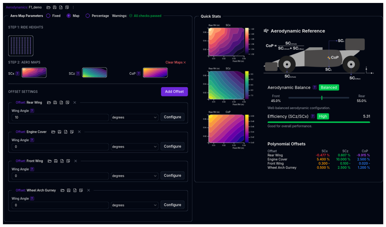 Configure your vehicle's aerodynamic characteristics including downforce, drag, and aerodynamic balance. Choose between fixed coefficients, ride height-dependent maps, or percentage-based adjustments.
Overview
The Aerodynamics setup defines:
- Aerodynamic Mode - Fixed, Map (Standard/Split), Percentage, or Expression (Beta) configuration
- Core Parameters - SCx (drag area), SCz (lift area), CoP (center of pressure)
- Ride Height Sensitivity - How aero changes with front/rear ride heights (Map and Percentage modes)
- Offset Settings - Offset angle adjustments using expression-based or map-based offsets, optionally varying with the aero state
Positive Downforce Convention
In motorsport, positive SCz values represent downforce (negative lift). This is opposite to aerospace convention but standard in vehicle dynamics.
Aerodynamic Modes
Choose the mode that best fits your available data and tuning needs.
Mode 1: Fixed (Coefficient)
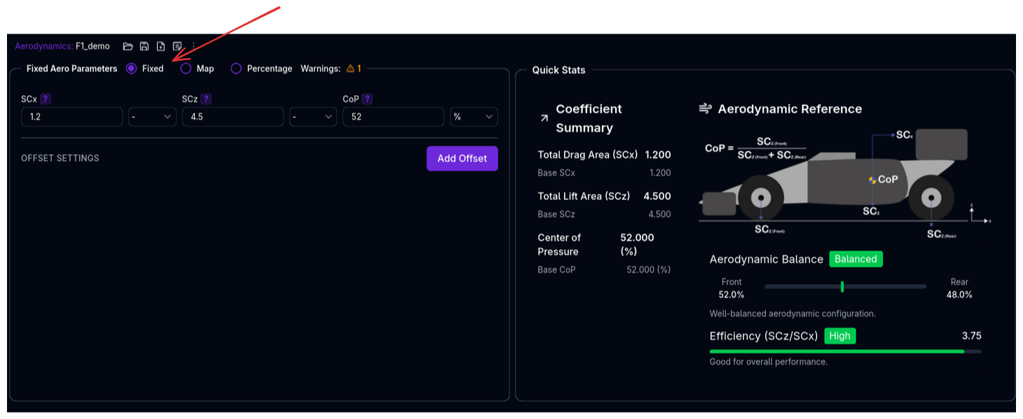
Simple fixed values for drag, downforce, and balance. Best for initial setup or when aero data is limited.
Use when: - You have single-point aero data (e.g., manufacturer specs) - Testing baseline vehicle behavior - Ride height sensitivity is negligible
See also: Standard vs Split Modeling for input parameter options.
Mode 2: Map (map2d)
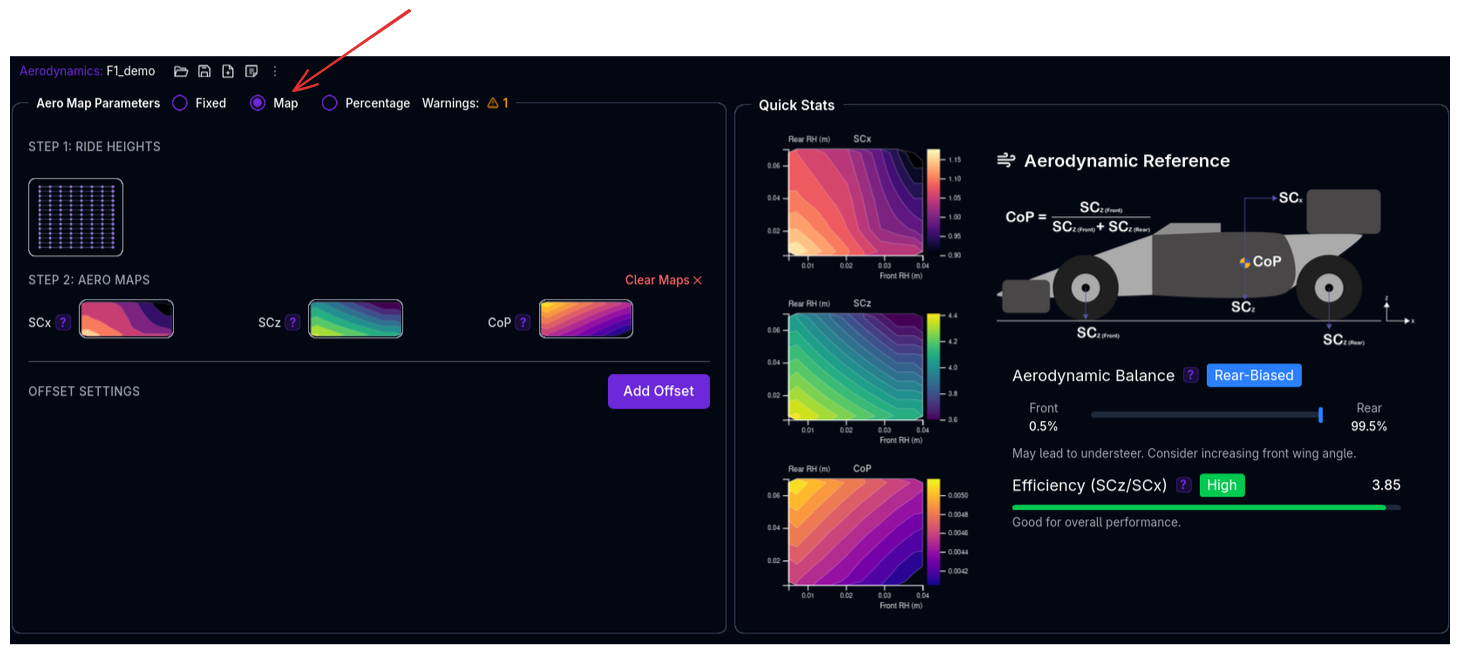 Full 2D maps defining how aero changes with front and rear ride heights. Most accurate for advanced setups.
Use when: - You have CFD or wind tunnel data across ride height ranges - Modeling ride height-sensitive aero platforms - Maximum accuracy is required
See also: Standard vs Split Modeling for input parameter options.
Mode 3: Percentage
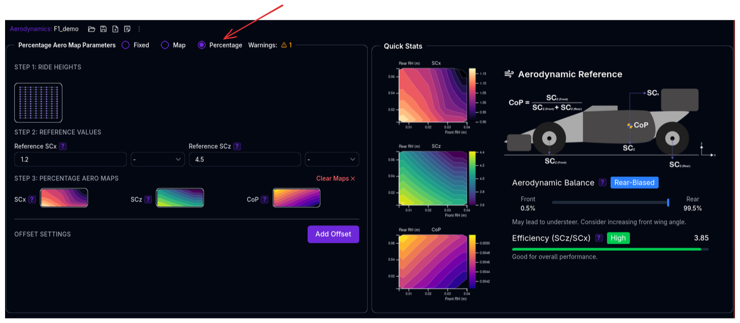
Reference values modified by percentage maps based on ride height. Convenient for relative adjustments.
Use when: - You have a baseline configuration and want to model percentage changes - Exploring aero sensitivity studies - Easier to understand percentage changes vs absolute values
See also: Standard vs Split Modeling for input parameter options.
Standard vs Split Modeling
All four modes (Fixed, Map, Percentage, Expression) support two modeling approaches:
Standard Modeling
In Standard modeling, the inputs are defined as:
- SCx - Drag area
- SCz - Total downforce area
- CoP - Center of pressure (front axle proportion)
The standard approach uses a single 2D grid where both front and rear ride heights index into the same map.
Use when: - Your source data already reports total drag and downforce together (rather than a front/rear split) - Front and rear aero interact strongly (e.g. wake or ground-effect coupling), so indexing on both ride heights at once is more accurate - You want fewer inputs to maintain than the Split approach
Split Modeling
In Split modeling, the inputs are defined as: - SCx - Drag area - SCzF - Front downforce area - SCzR - Rear downforce area
The split approach uses separate maps for front and rear aero coefficients. Front aero is indexed by front ride height only; rear aero is indexed by rear ride height only.
Use when: - You have front and rear aero data from different sources (e.g., front wing tunnel, rear wind tunnel) - Modeling asymmetric aero platforms where front and rear behave independently - Simplified mapping when front-rear interaction is negligible
Output:
- Total downforce is calculated as: SCz = SCzF + SCzR
Mode 4: Expression (Beta)
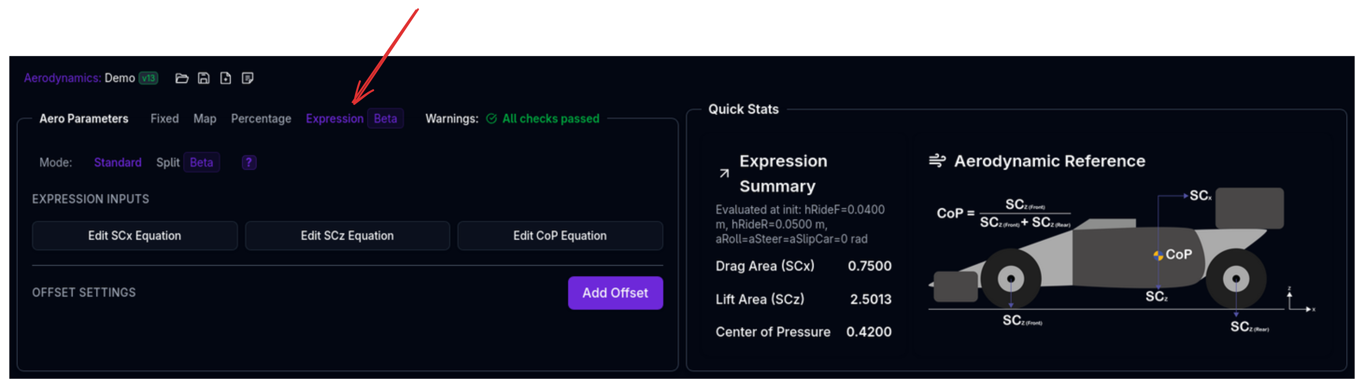
Expression mode allows you to define aero parameters using mathematical expressions that reference other channels (e.g., ride heights, velocity, steering angle). This enables dynamic aero modeling where coefficients change based on vehicle state.
Use when: - Modeling aero that responds to vehicle dynamics (e.g., ride height + speed effects) - Complex interactions between multiple parameters - Custom aero curves that don't fit standard polynomial or map approaches
See also: Standard vs Split Modeling for input parameter options.
Configuration:
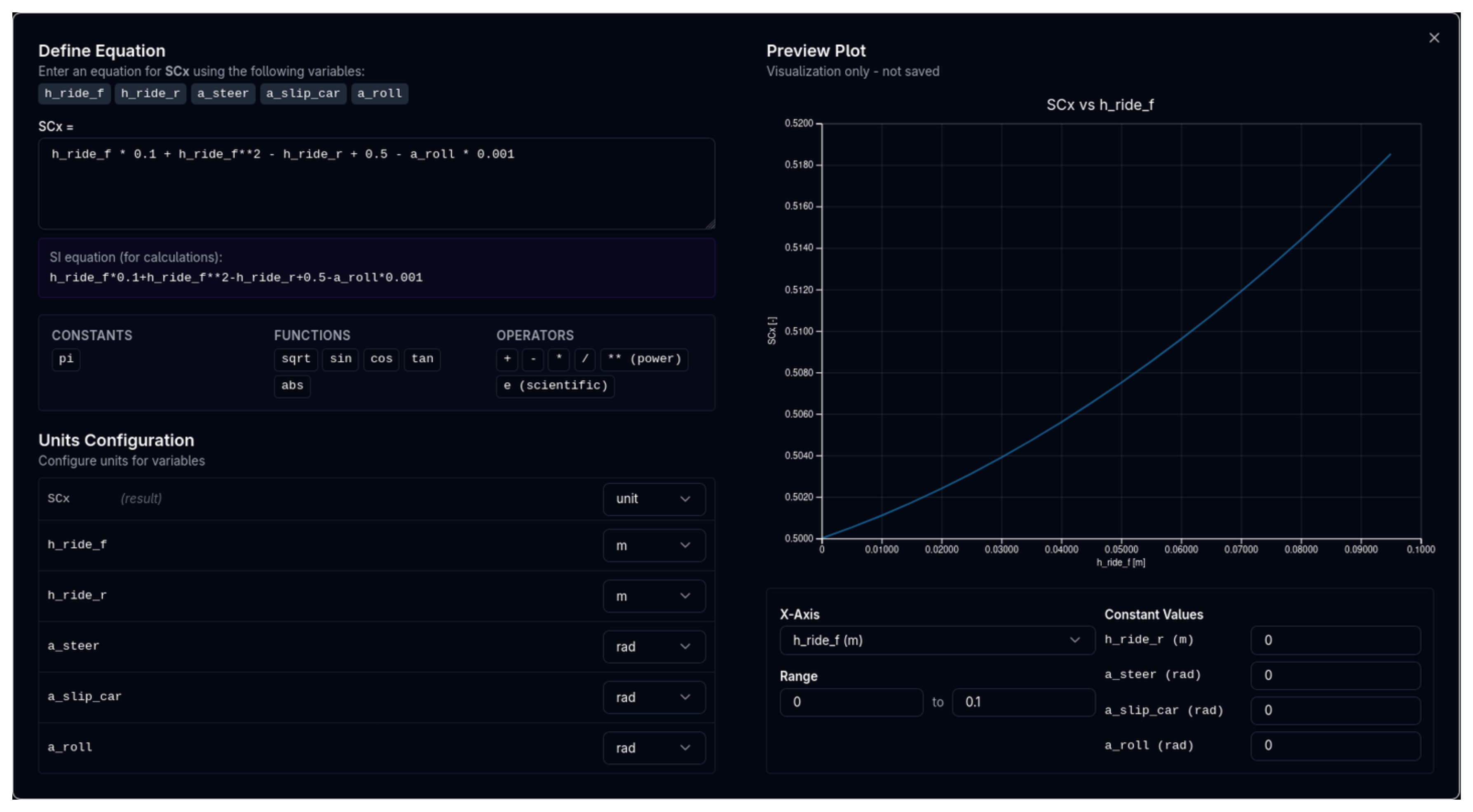
- Define Input Channels - Which vehicle state channels to reference (e.g.,
h_ride_f,h_ride_r,a_roll,a_yaw,a_steer) - Write Expressions - Mathematical formulas using the input channels
- Define Operating Range - Valid ranges for inputs to prevent extrapolation
Expression Syntax:
- Basic math: +, -, *, /, ^
- Functions: sqrt(), sin(), cos(), tan(), abs(), sign()
- Channel references: h_ride_f, h_ride_r, a_roll, a_yaw, a_steer, etc.
Example (Standard Modeling):
SCx = 0.75 + 0.005 * abs(h_ride_f - h_ride_r)
SCz = 2.5 + 0.02 * h_ride_f + 0.01 * h_ride_r
CoP = 0.42 - 0.001 * h_ride_f + 0.001 * h_ride_r
Example (Split Modeling):
SCx = 0.75 + 0.005 * abs(h_ride_f - h_ride_r)
SCzF = 1.5 + 0.02 * h_ride_f + 0.001
SCzR = 1.0 + 0.01 * h_ride_r + 0.001
Available Input Channels:
| Channel | Description |
|---------|-------------|
| h_ride_f | Front ride height |
| h_ride_r | Rear ride height |
| a_roll | Roll angle |
| a_yaw | Vehicle heading relative to the wind (wind-corrected yaw angle) |
| a_steer | Steering angle |
| n_engine | Engine angular velocity. The solver reads rad/s; the unit dropdown also offers RPM and converts for you. |
| v_pitot | Wind-corrected airspeed — the speed the dynamic pressure is built from. This is not the speed over the road; the two differ whenever there is wind. |
Expression Mode Beta
Expression mode is in beta. Performance may vary for complex expressions. Use Standard or Split map modes for production simulations where maximum performance is critical.
Core Aerodynamic Parameters
SCx (Drag Area)
The drag coefficient multiplied by frontal area: Cd × A
Used in drag force equation: Drag = ½ρv²(CdA) where ρ is air density and v is velocity.
Typical values: - Formula cars (high downforce): 0.8-1.2 m² - GT cars: 0.6-0.9 m² - Touring cars: 0.6-0.8 m² - Road cars: 0.5-0.7 m²
Positive Values Only
Drag always opposes motion. SCx values are always positive.
SCz (Lift Area)
The lift coefficient multiplied by reference area: Cl × A
Used in lift force equation: Lift = ½ρv²(ClA) where ρ is air density and v is velocity.
In motorsport: Positive values = Downforce (negative lift)
Typical values: - Formula cars (high downforce): 2.5-4.0 m² - GT cars (LMP, GTE): 1.5-3.0 m² - Touring cars: 0.3-0.8 m² - Road cars: 0.0-0.2 m²
Negative SCz = Lift (Undesirable)
Negative SCz values indicate lift instead of downforce. The platform will warn if this occurs, as it's usually unintended in racing.
CoP (Center of Pressure)
The proportion of total downforce acting on the front axle, expressed as a decimal (0-1) or percentage (0-100%).
Formula: - Front downforce = Total downforce × CoP - Rear downforce = Total downforce × (1 - CoP)
Examples: - CoP = 0.7 (or 70%) → 70% front, 30% rear (forward balance) - CoP = 0.5 (or 50%) → 50% front, 50% rear (neutral balance) - CoP = 0.35 (or 35%) → 35% front, 65% rear (rearward balance)
Typical values: - Formula cars: 0.40-0.50 (balanced to slight rear bias) - GT cars (front-engine): 0.45-0.55 (more forward) - GT cars (mid-engine): 0.35-0.45 (more rearward)
Aero Balance and Handling
- Higher CoP (>0.5): More front downforce, reduces understeer at high speed
- Lower CoP (<0.5): More rear downforce, reduces oversteer at high speed
- Adjust CoP to tune high-speed balance without changing total downforce
Configuration: Fixed Mode
The simplest configuration for constant aerodynamic properties.
Setup Steps
- Select Fixed mode from the radio buttons
- Enter SCx (drag area)
- Enter SCz (downforce area)
- Enter CoP (front downforce proportion)
Example Configuration
GT3 Car - Fixed Aero: - SCx: 0.75 m² - SCz: 2.8 m² - CoP: 0.42 (42% front, 58% rear)
At 200 km/h (55.56 m/s) with air density 1.225 kg/m³: - Total downforce: ½ × 1.225 × 55.56² × 2.8 = 5,308 N (541 kg) - Front downforce: 5,308 × 0.42 = 2,229 N (227 kg) - Rear downforce: 5,308 × 0.58 = 3,079 N (314 kg) - Drag force: ½ × 1.225 × 55.56² × 0.75 = 1,420 N (145 kg)
Configuration: Map Mode
Full ride height-dependent aero maps for maximum accuracy.
Setup Steps
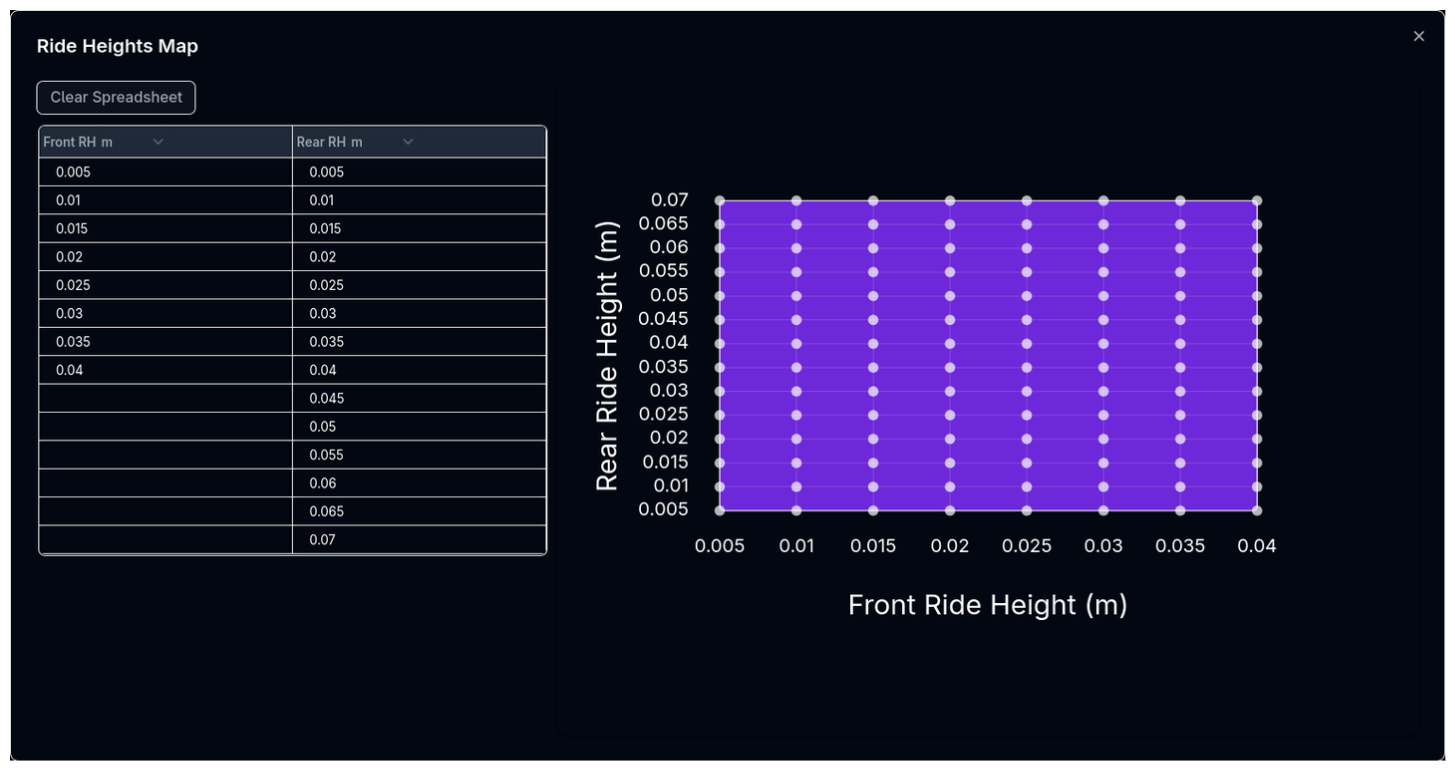
Step 1: Define Ride Heights
- Click Ride Heights button
- Enter Front RH array - e.g., [20, 30, 40, 50] mm
- Enter Rear RH array - e.g., [30, 40, 50, 60] mm
- Platform creates a grid: 4 front × 4 rear = 16 combinations
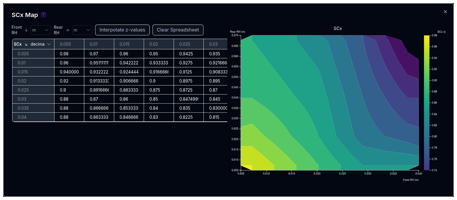
Step 2: Create Aero Maps
For each of SCx, SCz, and CoP:
- Click the parameter button (e.g., SCx)
- Fill in the 2D table with values at each (front RH, rear RH) combination
- Values are interpolated during simulation
Example Configuration
Formula Car - Ride Height Sensitive:
Ride Heights: - Front: [20, 30, 40] mm - Rear: [30, 40, 50] mm
SCz Map (downforce area, m²):
| Front RH → | 20mm | 30mm | 40mm |
|---|---|---|---|
| Rear 30mm | 3.8 | 3.5 | 3.2 |
| Rear 40mm | 3.5 | 3.3 | 3.0 |
| Rear 50mm | 3.2 | 3.0 | 2.8 |
Pattern: Lower ride height = more downforce (ground effect)
CoP Map (front proportion, decimal):
| Front RH → | 20mm | 30mm | 40mm |
|---|---|---|---|
| Rear 30mm | 0.45 | 0.42 | 0.40 |
| Rear 40mm | 0.48 | 0.45 | 0.43 |
| Rear 50mm | 0.50 | 0.48 | 0.46 |
Pattern: Lower front RH or higher rear RH = more forward CoP
Aero Map Strategy
- Lower ride heights typically generate more downforce (ground effect)
- Rake (front low, rear high) often increases downforce but shifts CoP forward
- Use CFD or wind tunnel data when available
- Start with conservative maps and refine based on track data
Fixing a map that is the wrong way round
A 2D map is stored one row per rear ride height and one column per front ride height. A grid whose rows and columns have been swapped holds exactly the same number of values as a correct one, so a transposed map is not something the grid size alone can catch — the car simply runs with the wrong coefficient at every ride height.
The map editor has an Orientation menu offering three repairs:
| Action | Effect |
|---|---|
| Transpose | Swaps rows and columns. |
| Flip rows | Reverses the row order. |
| Flip columns | Reverses the column order. |
All three act on the values only and leave the ride-height axes alone — they exist to realign a grid with the axes it is stored against. Each is its own inverse, and none adds, drops or alters a value, so they are safe to try and safe to undo.
The editor also checks your grid against your axes and tells you what it finds:
| Badge | Meaning |
|---|---|
| Looks transposed | The grid is exactly the transpose of your axes. Both shapes are named, and Transpose is marked as suggested in the Orientation menu. |
| Shape mismatch | The grid matches neither your axes nor their transpose. |
| Square axes | Your front and rear axes have the same number of points, so a correct grid and a transposed one are the same shape and cannot be told apart automatically. |
Square axes need judging by eye
Where front and rear ride-height arrays are the same length, nothing shape-based can distinguish a correct map from a transposed one, and transposing a working map would break the car. Judge it by physics instead: raising front ride height should move CoP rearward, and raising rear ride height should move it forward. If both gradients carry the wrong sign, the map is transposed.
Maps that were repaired for you
A number of cars — including the Formula Student template and everything cloned from it — shipped with transposed aero maps. Every affected map whose axes differ in length has been corrected automatically, and the teams involved received an in-app notification naming the maps that changed. Lap times and balance figures for those cars will differ from before, because the earlier figures were wrong. No values were added or removed; only their positions changed.
Maps on square axes could not be corrected automatically — check those by hand using the test above.
Configuration: Percentage Mode
Reference values modified by percentage changes based on ride height.
Setup Steps
Step 1: Define Ride Heights
Same as Map mode - define front and rear ride height arrays.
Step 2: Set Reference Values
- Enter Reference SCx - Baseline drag area
- Enter Reference SCz - Baseline downforce area
Step 3: Create Percentage Maps
For each parameter: 1. Click the parameter button 2. Fill percentage changes relative to reference 3. Final value = Reference × (1 + Percentage/100)
Example Configuration
GT Car - Percentage Adjustments:
References: - Reference SCx: 0.75 m² - Reference SCz: 2.5 m²
Ride Heights: - Front: [40, 50, 60] mm - Rear: [50, 60, 70] mm
SCz Percentage Map (%):
| Front RH → | 40mm | 50mm | 60mm |
|---|---|---|---|
| Rear 50mm | +15% | +5% | 0% |
| Rear 60mm | +10% | 0% | -5% |
| Rear 70mm | +5% | -5% | -10% |
At Front 40mm, Rear 50mm: - SCz = 2.5 × (1 + 15/100) = 2.5 × 1.15 = 2.875 m²
At Front 60mm, Rear 70mm: - SCz = 2.5 × (1 - 10/100) = 2.5 × 0.90 = 2.25 m²
CoP Percentage Map: Direct CoP values (0-1), not percentages of reference.
CoP in Percentage Mode
The CoP map in percentage mode contains direct CoP values (0-1), not percentage changes. This is because CoP represents a proportion, not a multiplied quantity.
Offset Settings
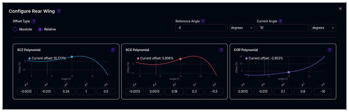
Add expression-based or map-based offsets to model aerodynamic surface adjustments (e.g., rear wing angle, front flap trim, DRS).
Understanding the Parent-Child Relationship
The Aerodynamics component uses a parent-child structure where offset components are optional children that modify the parent's base aerodynamic values.
graph TD
    Aero[Aerodynamics<br/>Base: SCx, SCz, CoP<br/>Mode: Fixed/Map/Percentage]
    Aero -->|Optional| W1[Rear Offset]
    Aero -->|Optional| W2[Front Flap]
    Aero -->|Optional| W3[DRS Offset]

    W1 -->|Offset Expressions| W1_Data[Angle: 5°<br/>Type: Relative<br/>SCz: +22.5%<br/>SCx: +15%<br/>CoP: -5%]
    W2 -->|Offset Expressions| W2_Data[Angle: 3°<br/>Type: Absolute<br/>SCz: +0.15<br/>SCx: +0.05<br/>CoP: +0.02]

    style Aero fill:#6366f1,color:#fff
    style W1 fill:#10b981,color:#fff
    style W2 fill:#10b981,color:#fff
    style W3 fill:#10b981,color:#fff
    style W1_Data fill:#f3f4f6,color:#000
    style W2_Data fill:#f3f4f6,color:#000
How it works:
- Aerodynamics (Parent) contains the base aero data configured in one of three modes (Fixed, Map, or Percentage)
- Offsets (Children) are optional offset components, each representing an adjustable aerodynamic surface
- Final values = Base aero + Sum of all offsets:
Example: - Base aero: SCz = 2.5 m², SCx = 0.75 m², CoP = 0.42 - Rear Offset: +22.5% SCz, +15% SCx, -5% CoP (Relative) - Front Flap: +0.15 SCz, +0.05 SCx, +0.02 CoP (Absolute) - Final SCz = 2.5 × 1.225 + 0.15 = 3.21 m² - Final SCx = 0.75 × 1.15 + 0.05 = 0.91 m² - Final CoP = 0.42 × 0.95 + 0.02 = 0.419
Component Hierarchy
See Component Hierarchy for more details on how parent-child relationships work throughout ARD.
What Offsets Do
Offsets adjust the base aero properties (from Fixed/Map/Percentage modes) based on aerodynamic surface angle changes.
Each offset (SCz, SCx, and CoP) is defined by a free-form expression. Most
offsets are written in terms of a single variable, x, which is the current
value of the offset's input (e.g. the current wing angle). The platform plots
the resulting curve in real time as you type.
Expression syntax:
- Variables: x — the offset's own input value — plus the aero-state
variables described below
- Operators: + - * / ** (power), e.g. x**2
- Functions: sqrt, sin, cos, tan, abs, sign
- Constants: pi
For example, 0.5*x**2 + 2.0*x describes a quadratic offset. Because the expression is free-form, it is not restricted to polynomials — relationships such as sqrt(x) or sin(x) are equally valid.
Offset Types: - Absolute: Final = Base + Offset - Relative: Final = Base × (1 + Offset/100)
Offsets That Vary With the Aero State
An offset written only in terms of x is a fixed value: it is computed once
from the input and added to (or scales) the base. When an aerodynamic device's
effect depends on the car's attitude — a floor edge that stalls with ride
height, say — the offset can instead be written against the same variables as
the main aero expression:
h_ride_f, h_ride_r, a_steer, a_yaw, a_roll, n_engine, v_pitot
Such an offset is re-evaluated at every point in the simulation rather than
collapsed to a single number. It is still applied to the base aero exactly like
any other offset — the composition rules above are unchanged. For example, with
a base SCz of h_ride_f + h_ride_r and an absolute offset of 0.02*a_yaw,
the car runs:
and as a relative offset, the expression is treated as a percentage:
Works everywhere
Aero-state offsets carry no special requirements. They work with any
base map type — Expression, Map, Percentage or a fixed coefficient — and at
either application point, Chassis or Hub. Each coefficient is judged on
its own: writing SCz against a_yaw does not change how that offset's
SCx or CoP behave.
Offsets never modify each other
Every offset applies to the base value once, so the percentages from
multiple relative offsets add rather than compounding, and an absolute
offset is never scaled by a relative one. Two +10% offsets give
Base × 1.20, not Base × 1.10 × 1.10.
The one exception is map-based offsets, which are baked into the base aero map itself — a relative expression offset therefore scales them along with the rest of the map.
Because these offsets vary with the operating point, they have no standalone curve to plot; the offset dialog marks them as state-dependent and shows their effect in the aero summary instead, evaluated at the static ride heights.
Map-Based Offsets
In addition to expression-based offsets, you can define offsets using 2D lookup tables. Map-based offsets interpolate values from a grid of reference angles versus another variable (e.g., ride height or velocity).
Use when: - You have test data mapping angle to aero at multiple conditions - A single expression doesn't fit your data well - Offsets vary with operating conditions
Configuration: 1. Enable Map-Based toggle on an offset 2. Define Reference Angles - Array of angle values 3. Define Map Variables - Second dimension (e.g., ride height, velocity) 4. Fill the 2D table with offset values at each combination
Hub vs Chassis Application Points
Aero offsets can be applied at different reference points, affecting how they interact with the suspension and vehicle dynamics:
Hub Application: - Offsets are applied at the wheel hub - Aero forces act directly on the hub not affecting the sprung geometry. - Better for modeling unsprung aerodynamic elements.
Chassis Application: - Offsets are applied at the sprung components. - Aero forces are transferred through the suspension geometry - Better for modeling overall chassis attached elements
Configuration: - Select Application Point in offset settings: Hub or Chassis - Default: Chassis
Choosing Application Point
Use Hub for unsprung components (e.g., tyres). Use Chassis for overall vehicle aero changes or when the aero element is mounted to the chassis structure.
Adding an Offset
There are two ways to add an offset:
- Create New — Click Create New, name the offset (e.g., "Rear Offset", "Front Flap"), then click the gear icon to configure it
- Add Existing — Click Add Existing to attach an offset that already exists in your team's library instead of building a duplicate. Offsets already attached to this aero are greyed out in the picker so you cannot add the same one twice
Configuring an Offset
Angle Settings: - Reference Angle - Base angle where offset is zero (e.g., 0°) - Current Angle - Actual wing angle (e.g., 5°)
Offset Type: - Absolute - Adds/subtracts directly from base values - Relative - Adds/subtracts as a percentage
Offset Expression:
For each of SCz, SCx, and CoP, enter an expression in terms of x (see What Offsets Do for available operators, functions, and constants).
The platform plots the resulting curve in real-time.
Example: Rear Offset Adjustment
Scenario: Increase rear wing from 0° (reference) to 5° (current).
Offset Type: Relative (percentage)
SCz Expression (more downforce with higher angle):
- Expression: 0.5*x**2 + 2.0*x
- At x=5: offset = 0.5(5²) + 2.0(5) = 12.5 + 10.0 = 22.5%
SCx Expression (more drag with higher angle):
- Expression: 0.3*x**2 + 1.5*x
- At x=5: offset = 0.3(5²) + 1.5(5) = 7.5 + 7.5 = 15.0%
CoP Expression (shifts rearward with more rear wing):
- Expression: -0.1*x**2 - 0.5*x
- At x=5: offset = -0.1(5²) - 0.5(5) = -2.5 - 2.5 = -5.0%
If base values are SCz=2.5 m², SCx=0.75 m², CoP=0.42: - Final SCz = 2.5 × (1 + 22.5/100) = 3.0625 m² (+22.5% downforce) - Final SCx = 0.75 × (1 + 15/100) = 0.8625 m² (+15% drag) - Final CoP = 0.42 × (1 - 5/100) = 0.399 (39.9% front, shifted rearward)
When to Use Offsets
- Modeling adjustable rear wings or front flaps
- Simulating setup changes without recreating entire aero maps
- Testing wing angle sensitivity
- DRS (Drag Reduction System) modeling
Multiple Offsets
You can add multiple offsets (e.g., front + rear wing). The platform sums all absolute offsets and all relative offsets separately, then applies both.
How Aerodynamics Relates to Other Components
Chassis
Chassis reference ride height defines the baseline. Initialization race-ready ride height is used to lookup values in aero maps during simulation.
Suspension
Suspension compression/extension during cornering, braking, and acceleration changes ride heights dynamically. Aero maps model how downforce and balance shift with these ride height changes.
Track
Different tracks require different aero setups: - High-speed tracks (Monza, Spa) → Lower drag, moderate downforce - Twisty tracks (Monaco, Hungary) → Maximum downforce, higher drag acceptable - Balanced tracks (Silverstone, Barcelona) → Compromise between drag and downforce
Configuration Workflow
Recommended Workflow
-
Start with Fixed Mode
- Use manufacturer data or estimates
- Get baseline vehicle behavior
-
Choose Your Mode
- Fixed: If aero is not ride height sensitive
- Map: If you have CFD/wind tunnel data
- Percentage: If you want relative adjustments
-
Configure Base Aero
- Fixed: Enter SCx, SCz, CoP
- Map: Define ride heights, create 2D maps
- Percentage: Set references, create percentage maps
-
Add Offsets (Optional)
- Model wing angle adjustments
- Configure polynomials for each offset
- Use Absolute or Relative as appropriate
-
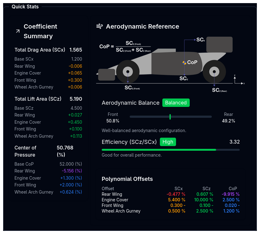
Review Quick Stats
- Check calculated downforce at typical speeds
- Verify aero balance (front/rear distribution)
- Review on desktop (Quick Stats panel, right side)
- Figures come from the solver at your car's static ride heights and refresh automatically each time you save. The panel shows a loading state while it recalculates, a stale badge when you have unsaved edits, and a message telling you to save if the figures aren't available yet
- The Offset Contributions table below the panel breaks the result down into Base, each individual offset, and Total, exactly as the solver computes it
- Validate Configuration
- Check Tree View for warnings
- Address any flagged issues
- Test in simulation
Validation Warnings
The platform validates aerodynamic parameters and warns for:
Offset/Offset Warnings: - Offset angle >20° (unusually high) - Offset angle differs >15° from reference (large delta) - Absolute offsets: SCz >1.0, SCx >0.5, CoP >0.2 (very large) - Relative offsets: >25% (very large percentage change)
System Warnings: - Combined offsets too large (all offsets summed) - Negative SCz values (lift instead of downforce) - SCx <0.15 (unrealistically low drag) - SCx >2.0 (unrealistically high drag) - CoP <0.2 or <20% (very rearward aero balance) - CoP >0.8 or >80% (very forward aero balance)
Viewing Warnings
Warnings appear in the Tree View next to the Aero component. Click the warning icon to view details.
Tips & Best Practices
Start Simple, Add Complexity
Begin with Fixed mode to establish baseline behavior. Add Map mode only when you have validated data and need ride height sensitivity.
CoP Tuning for Balance
Adjust CoP (not total downforce) to tune high-speed understeer/oversteer. Increase CoP to reduce high-speed understeer, decrease to reduce oversteer.
Drag vs Downforce Trade-off
More downforce usually means more drag. Balance corner speed gains (downforce) vs straight-line speed losses (drag) based on track layout.
Use Percentage Mode for Sensitivity Studies
Percentage mode makes it easy to explore "what if" scenarios: "What if I lose 10% downforce at low ride height?"
Offset Offsets for Quick Adjustments
Use offsets to model wing angle changes without recreating entire aero maps. Great for setup optimization.
Validate CFD/Wind Tunnel Data
Always cross-check simulation results with real-world testing. CFD and wind tunnel data can have errors or not account for on-track conditions.
Negative Downforce is Usually Wrong
If you see negative SCz warnings, verify your data. Racing cars should generate downforce (positive SCz), not lift.
Related Topics
- Chassis Setup - Reference ride heights for aero baseline
- Initialization Setup - Race-ready ride heights used in aero lookups
- Suspension Setup - How suspension affects ride height dynamically
- Track Selection - Track-specific aero requirements
- Coordinate System - Understanding positive/negative conventions