Anti-Roll Bars
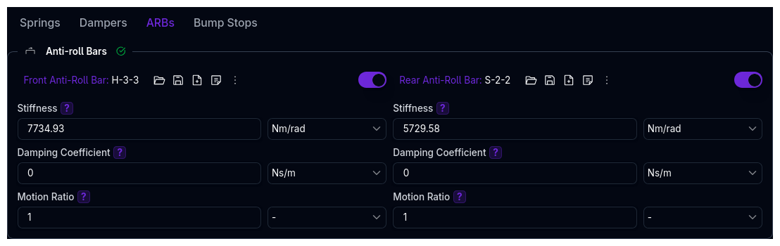
Configure anti-roll bars (ARBs) for front and rear axles. ARBs resist body roll by coupling left and right wheel movements, redistributing lateral load transfer between the front and rear axles.
ARBs are optional — they are toggled on or off independently per axle. When disabled, no roll stiffness contribution is added from the ARB.
Parameters
| Parameter | Description | Unit |
|---|---|---|
| Stiffness | Torsional stiffness of the anti-roll bar | Nm/rad |
| Damping Coefficient | Rotational damping coefficient of the anti-roll bar, about the bar | Nms/rad |
Check this value on existing setups
The Damping Coefficient was previously offered in distance-based units (Ns/m, Ns/mm, lbs/in), which was wrong — the quantity is torsional, about the bar, and its correct unit is Nms/rad.
If you ever entered this value using the Ns/mm or lbs/in option, the number now displayed has been rescaled to preserve the same physical value, so it will not read as you typed it. Open the page and confirm it against your intended figure.
ARB Motion Ratio
The ARB motion ratio is the single most-asked-about number on this page, and it is not the same kind of quantity as a spring or damper motion ratio. It is defined against roll, not against wheel travel:
It is dimensionless, but because both terms are angles it is not comparable to the spring or damper motion ratio (which is inboard travel per unit wheel travel, typically 0.3–1.5). Values of 5–15 rad/rad are entirely normal for a stiff bar on a short lever arm. A high number is not by itself a sign that something is wrong.
The motion ratio is not entered on this page. It is either solved from your ARB pickup-point geometry or supplied manually in Kinematics — see Where the value comes from below.
Where the value comes from
| ARB type (Kinematics) | Source of the motion ratio |
|---|---|
| U-Bar | Solved from the arb_ax, arb_lp, arb_rp pickup points |
| T-Bar | Solved from the T-bar pickup points (tbar_cp, tbar_cp2, tbar_ap, hsrp, hsbp) |
| None | Taken from the manual ARB motion-ratio field in Kinematics (constant or a curve vs roll angle) |
Geometry always wins where it exists. If the axle has an ARB architecture with pickup points, the manual field is ignored — the solved value is used.
How the geometric value is solved
Because the ARB couples the two sides of the axle, it cannot be solved one corner at a time. The platform:
- Sweeps the axle through roll, ±0.05 rad (±2.9°) about the reference position.
- Solves the left and right corners together at each step of the sweep.
- Reads the bar's own twist directly from the geometry at each step — the joint rotation of the torsion tube for a U-bar, the closure angles of the torsion element for a T-bar — referenced to zero twist at zero roll. This builds a twist-vs-roll curve, which is the bar's primitive quantity.
- Takes the local derivative of that curve to get the motion ratio.
Because the motion ratio is a derivative of a solved curve rather than a single constant, a non-linear installation correctly reports a motion ratio that changes with roll angle. The twist curve is what the platform stores; everything else about the bar is derived from it, so the reported twist, moment and roll rate cannot disagree with each other.
U-bar twist is the full twist across the tube
For a U-bar the reported twist is the relative twist between the two arms:
That is, both arms' rotations against the centre, not one side's rotation. This is the most common reason a reported motion ratio looks about twice what was expected from a hand calculation, and it is deliberate: it pairs with a Stiffness entered as the torsion tube's moment per unit of that same relative twist.
Sanity-checking a value by hand
For a conventional U-bar with a drop link driven off the rocker or wishbone:
Example — 1.6 m track, drop link at 0.5 of wheel travel, 100 mm lever arm:
Short lever arms and a high drop-link ratio push the number up quickly, which is why the front axle is often the larger of the two. If the reported value is within roughly this ballpark, the geometry is behaving.
The stiffness and the twist must use the same definition
Stiffness on this page is the bar's torsional stiffness in Nm/rad (or Nm/deg) — moment per unit of the relative twist between the two arm ends, the same twist reported as aARBF / aARBR. If your bench figure was measured with one arm clamped and only the other twisted, it is defined against half the twist and will need converting before it is entered. A mismatched definition shows up as a roll stiffness out by a factor of two, not as an obviously wrong motion ratio.
Roll Stiffness Contribution
The bar's contribution is taken from its stored elastic energy, U = ½ × k × twist², so the moment it develops at a sprung roll angle φ is:
When the twist curve is linear in roll — a constant motion ratio, which covers a manual value and most U-bar installations — this reduces exactly to the textbook form:
The two forms only part company when the twist curve bends, which happens on large-motion T-bar geometries. In that case the energy-based form above is the one the platform uses, because it is the moment the bar actually develops.
The damping contribution has no such curvature term and is exact in the product form:
Total axle roll stiffness
The bar is added to the springs' contribution to give the axle roll rate:
where corner rate is the sum of the left and right wheel rates on that axle. The spring term is the standard result: in roll each wheel deflects ±(track/2) × φ and reacts a moment of K_wheel × (track/2)² × φ, so the pair contributes K_wheel × track² / 2.
Channels to check
Every step of the chain is exported, so a value can be verified on a real run rather than argued about:
| Channel | Meaning |
|---|---|
maARBF, maARBR |
ARB motion ratio |
aARBF, aARBR |
ARB twist angle |
MARBF, MARBR |
ARB roll moment |
SARBF, SARBR |
ARB roll stiffness contribution |
aRollSprung |
Sprung roll angle the above are queried against |
SRollF, SRollR, SRollTotal |
Total axle and vehicle roll stiffness |
See the Channel Reference for the full list.
Troubleshooting
| Symptom | Likely cause |
|---|---|
| Motion ratio looks about 2× too high | The reported twist is the full relative twist across the tube — both arms. Check that Stiffness is defined against the same twist. |
| Motion ratio is very high (>15) | Short lever arm or a high drop-link ratio. Check against the hand estimate above before assuming a geometry error. |
| Motion ratio is zero, and the bar has no effect | The ARB geometry could not be solved — usually a missing or mis-entered pickup point. Check the pickup points in Kinematics. |
| Roll stiffness is out by a factor of two | Stiffness entered per-arm rather than across the bar, or entered in Nm/deg while intended as Nm/rad. |
| Motion ratio changes with roll and you expected it constant | Expected for a non-linear installation — the motion ratio is the derivative of the solved twist curve, not a single constant. |
Validation Warnings
| Condition | Warning |
|---|---|
| Stiffness is zero | Zero stiffness — ARB has no effect |
| Stiffness > ~500,000 Nm/rad (~8.7 kNm/deg) | Very stiff anti-roll bar |
Related Pages
- Suspension Overview — Component hierarchy and page layout
- Springs — Corner and heave spring configuration
- Kinematics — ARB motion ratio, motion ratios, and geometry