Ride Analysis (Virtual 4-Post)
The Ride Analysis simulation serves as a Virtual 4-Post Rig, allowing you to excite the vehicle's contact patches with various input signals and analyze the vertical dynamics response. It is essential for optimizing spring rates, damper curves, and analyzing ride comfort and mechanical grip over different road surfaces.
Overview
Just like a physical 4-post rig, this simulation applies vertical displacements to the tyres while the vehicle is stationary (or moving at a simulated speed for aerodynamic load context). It allows you to:
- Identify natural frequencies (heave, pitch, roll, wheel hop)
- Tune damping ratios for transient control
- Analyze frequency response (transmissibility) to optimize mechanical grip
- Evaluate ride comfort using ISO-standard road profiles
- Assess contact patch load variation (CPLV) to maximize traction
How Racing Teams Use It
The ride simulation is used to develop and validate the vertical dynamics of the vehicle:
- Damper development — Evaluate different damper curves (low-speed vs high-speed, bump vs rebound) and their effect on body control and contact patch consistency
- Spring rate selection — Confirm that chosen spring rates produce the desired ride frequencies before going to the track
- Ride frequency targeting — Verify that heave and pitch frequencies match design targets, and that their ratio promotes good transient behaviour
- Bump stop tuning — Use step or impulse inputs to check when bump stops engage and how the car recovers from large displacements
- Road surface evaluation — Use ISO 8608 noise profiles to predict how the car behaves on different road qualities (most circuits are class A or B; curbs can be class C-D)
- Correlation with physical rig — Compare simulation outputs against 4-post rig test data using custom input signals to validate the vehicle model
Strengths and Limitations
Strengths
- Full 7-DOF model — Captures heave, pitch, roll, and four unsprung mass (wheel hop) modes simultaneously
- Nonlinear capability — The non-linear mode captures progressive springs, bump stop engagement, and velocity-dependent damper curves
- Linearized analysis — The LTI mode enables analytical Bode plots for direct frequency and transmissibility analysis
- Multiple signal types — Chirp, noise, step, impulse, and custom inputs cover the full range of engineering questions
- Fast execution — Both modes complete in seconds
Limitations
- No lateral dynamics — The simulation is purely vertical; it does not capture roll induced by cornering or lateral load transfer
- No aerodynamic drag — Aero loads can provide a static preload context at a given speed, but there is no drag or speed-dependent simulation
- Stationary vehicle — The car does not travel along a track; road inputs are applied directly to the contact patches
Vehicle Setup Requirements
The ride simulation requires the following setup areas to be configured:
- Chassis — Total mass, mass distribution, sprung/unsprung masses, and moments of inertia (roll and pitch)
- Suspension — Springs, dampers, and optionally bump stops and anti-roll bars
- Tyres — Tyre vertical stiffness and damping rates
Check Your Inertias
The ride simulation is sensitive to roll and pitch moments of inertia. If these are not set, the simulation may produce unrealistic mode separation. See Chassis Setup for guidance.
Signal Types
The simulation offers several input signal generators to test different aspects of the suspension. These can be applied to individual corners (FL, FR, RL, RR) or all simultaneously.
1. Chirp
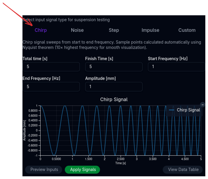
A sinusoidal sweep from a start frequency to an end frequency over a specified duration.
- Best for: Identifying resonant frequencies (natural modes) and analyzing frequency response magnitude/phase.
- Key Inputs: Start/End Frequency, Amplitude, Duration.
- Tip: A sweep from 0.1 Hz to 20 Hz covers most body and wheel modes of interest.
2. Noise (ISO 8608)
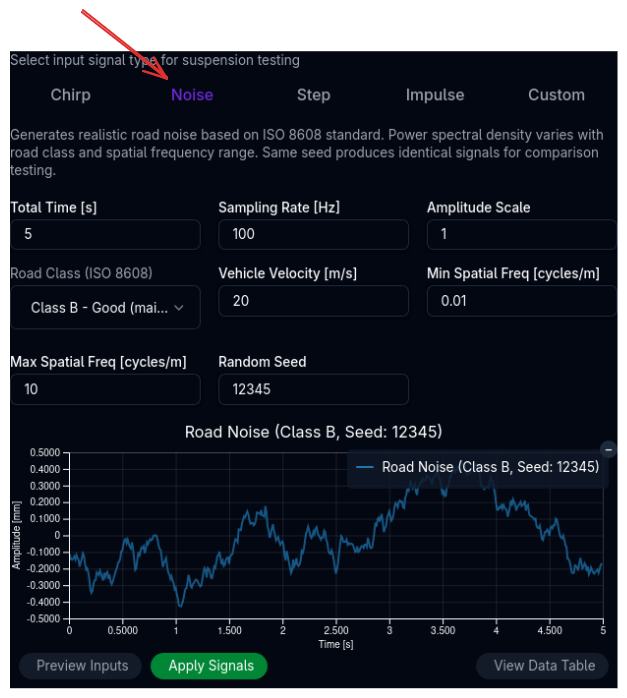
Generates a random road profile based on the ISO 8608 standard for road roughness.
- Best for: Real-world ride comfort analysis and evaluating contact patch load variation (grip) on specific road grades.
- Key Inputs:
- Road Class:
- A: Very good (motorway/highway)
- B: Good (main road)
- C: Average (minor road)
- D: Poor (damaged road)
- E: Very poor (unmaintained)
- Velocity: Simulates the speed at which the car traverses the profile (converts spatial frequency to temporal frequency).
- Seed: Ensures reproducibility between runs.
- Road Class:
3. Step
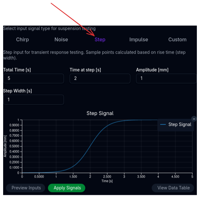
A sudden change in displacement that holds a constant value.
- Best for: Analyzing transient settling time, overshoot, and steady-state posture changes.
- Key Inputs: Step amplitude, rise time, and hold duration.
4. Impulse
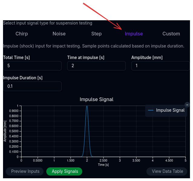
A momentary "kick" or bump (e.g., driving over a curb or debris).
- Best for: Checking shock absorption, high-speed damping, and bump stop engagement on sharp impacts.
- Key Inputs: Amplitude and impulse duration.
5. Custom
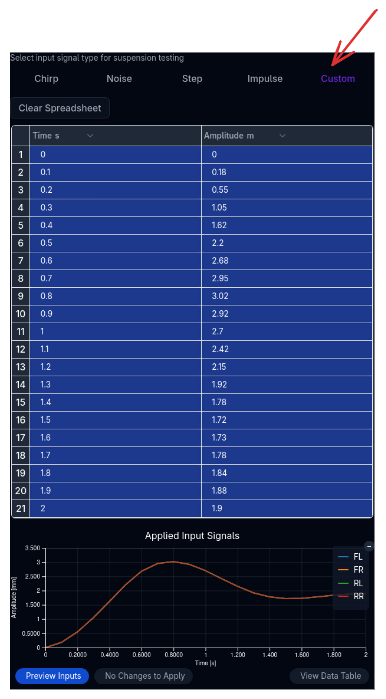
Allows you to define arbitrary input profiles for each corner via a spreadsheet interface.
- Best for: Replaying track data (e.g., specific curbs or bumps) or validating against physical rig tests.
Simulation Settings
Linearized Model vs. Full Non-Linear
You can choose between two mathematical approaches for the simulation using the checkbox in the control panel.
| Mode | Description | Pros | Cons |
|---|---|---|---|
| Linearized Model | Fits linear coefficients to springs and dampers using least-squares. Uses a state-space representation. | • Enables Bode plots (Frequency Domain) • Faster execution • Stable numerical behavior |
• Ignores bump stop gaps/progressive rates • Less accurate for large displacements |
| Non-Linear | Solves the full non-linear equations of motion. | • Captures bump stops, friction, and progressive rates • Accurate for large events |
• Slower execution • Frequency analysis requires FFT post-processing |
When to use which?
Use the Linearized Model for initial frequency analysis and identifying natural modes (Heave, Pitch, Roll). Use the Non-Linear (Default) mode (unchecked) when analyzing bump strikes, complex damper curves, or realistic road noise where non-linearities matter.
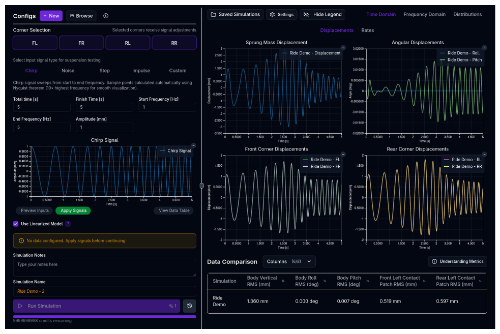
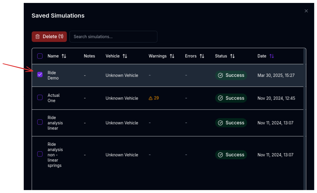
Running a Ride Simulation
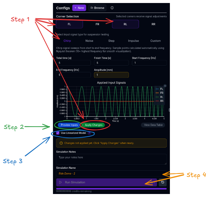
- Configure Inputs:
- Use the Signal Editor to select the corners to excite (FL, FR, RL, RR).
- Select a signal type (e.g., Chirp) and adjust parameters.
- Click Apply Signals.
- Preview: Toggle the Preview Inputs button to visualize the signal on the chart before running.
- Model Selection: Check "Use Linearized Model" if you specifically need linear frequency analysis tools (Bode plots), otherwise leave unchecked for the full physical model.
- Run: Click Run Simulation.
Analyzing Results
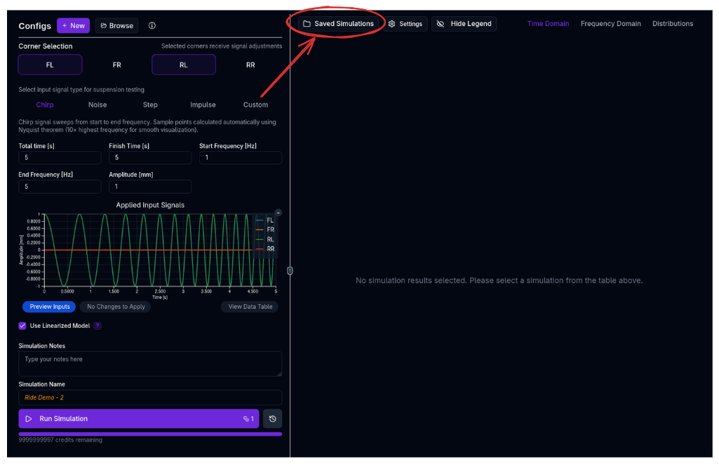
Results are organized into three domains in the results panel:
Time Domain
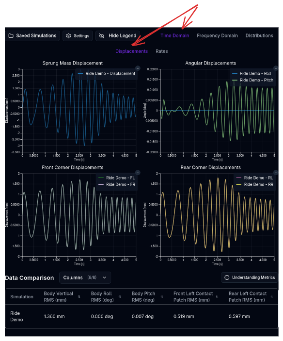
View the raw response of the vehicle over time. - Chassis: Heave, Pitch, Roll displacements and accelerations. - Suspension: Damper velocities, spring travel. - Tyres: Dynamic vertical load and deflection.
Frequency Domain
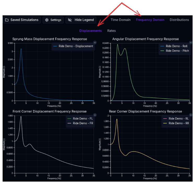
(Most effective with Linearized Model or Chirp inputs) - Transmissibility: How much input motion is transferred to the chassis at each frequency. Peaks indicate resonance. - Heave/Pitch/Roll Modes: Identify at what frequencies the body resonates. Target separation between heave and pitch frequencies to minimize "hobby-horsing." - Wheel Hop: Identify the unsprung mass resonance (typically 10-15 Hz).
Distributions
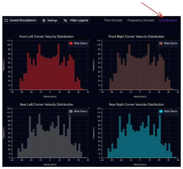
Histograms of key metrics, useful for statistical analysis of road noise. - Contact Patch Load Variation (CPLV): A narrower distribution implies more consistent grip. - Suspension Velocity: Check the usage of low-speed vs. high-speed damping regions (histogram of damper shaft speeds).
Tips & Best Practices
Target Frequencies
Typical targets for racing cars:
- Ride Frequencies: 1.5 - 3.0 Hz (High downforce cars are often stiffer, >3.0 Hz).
- Wheel Hop: Generally >12 Hz.
- Damping Ratios: 0.6 - 0.7 for critical damping is a common starting point, often stiffer in low-speed rebound for body control.
Pitch vs. Heave
Try to keep the Pitch Frequency slightly higher than the Heave Frequency (e.g., 1.2x). This helps the rear suspension settle faster than the front after a bump, keeping the car level and reducing pitch oscillation magnitude.
Related Topics
- Suspension Setup — Configure springs, dampers, and bump stops.
- Handling Simulation — Analyze lateral dynamics.
- Trace View — Visualise simulation results.