Straight Line Simulation
The Straight Line Simulation (SLS) calculates the aerodynamic forces, ride heights, suspension state, and tyre loads on your vehicle across a range of speeds — all at zero lateral and longitudinal acceleration. It is the simplest of the three QSS-family simulations and provides the clearest view of how your vehicle responds to increasing speed on a straight.
Overview
The SLS evaluates the vehicle in a pure straight-line condition: no steering, no cornering, no braking, no acceleration. At each speed in the defined range, it solves the coupled aero-suspension equilibrium to determine:
- How much downforce and drag the car produces
- How the ride heights change under aerodynamic load
- How the suspension compresses in response
- How the tyre loads redistribute
This makes it the ideal tool for understanding your vehicle's aero platform — the relationship between speed, downforce, ride height, and tyre load that underpins all other performance.
How Racing Teams Use It
The straight line simulation is a diagnostic and setup tool used in several key workflows:
- Ride height management — Understanding how much the car drops at high speed, and whether it approaches any physical limits (e.g., plank contact, floor stall)
- Aero platform analysis — Verifying that the aero map, suspension stiffness, and ride height targets work together as intended
- Spring rate selection — Evaluating whether the chosen spring rates provide the desired ride height control across the speed range
- Load distribution — Checking how tyre loads change with speed, which affects tyre temperature, wear, and mechanical grip
- Aero sensitivity studies — Comparing different aero configurations in a clean, isolated environment before introducing the complexity of cornering and lap simulation
- Correlation — Comparing simulated ride heights and aero loads against wind tunnel or CFD data
Why Straight Line Matters
Many engineers think of straight-line performance purely in terms of drag and top speed. In reality, the straight-line condition defines the starting platform from which cornering and braking performance are built. If the car's ride heights are wrong at speed, the aero balance will be wrong, and all cornering predictions will be affected. The SLS is the tool that catches these issues early.
Strengths and Limitations
Strengths
- Clean isolation — Removes all lateral and longitudinal coupling, making it easy to understand pure aero-suspension interaction
- Fast execution — Solves instantly across the speed range
- Converged aero-suspension coupling — Iteratively solves the ride height and aero force interaction until convergence, giving realistic ride heights rather than static estimates
- Direct comparability — Results can be directly compared to wind tunnel data, CFD predictions, or logged straight-line telemetry
Limitations
- No lateral or longitudinal dynamics — Does not capture cornering, braking, or acceleration effects on ride height or load distribution
- Symmetric assumption — The vehicle is assumed to be in a symmetric straight-line condition (no roll, no yaw)
- No powertrain — Does not evaluate engine/motor performance, gear selection, or acceleration capability
How the Simulation Works
The SLS iterates over the specified speed range. At each speed, it runs an aero-ride height convergence loop that couples the aerodynamic model with the suspension model.
flowchart TD
    A[Set speed] --> B[Calculate aero forces at current ride heights]
    B --> C[Calculate suspension response to aero loads]
    C --> D[Update ride heights]
    D --> E{Aero coefficients converged?}
    E -->|No| F[Recalculate aero at new ride heights]
    F --> C
    E -->|Yes| G[Calculate tyre loads]
    G --> H[Store results for this speed]
    H --> I[Next speed]
The Aero-Ride Height Convergence
This is the core physics loop shared by all QSS-family simulations. The problem it solves is fundamentally coupled:
- Aero forces depend on ride heights — Downforce and drag change as the car gets closer to or further from the ground (ground effect, diffuser performance, wing heights)
- Ride heights depend on aero forces — More downforce compresses the suspension further, lowering the car
- Suspension response is nonlinear — Springs may be progressive, bump stops may engage, and the installation ratio changes with displacement
The convergence loop resolves this circular dependency by iterating between the aero model and the suspension model until the aerodynamic coefficients (SCz, SCx, CoP) stabilise within tolerance. Convergence typically occurs within a few iterations.
Tyre Load Calculation
Once the aero-suspension state is converged, the simulation calculates the dynamic tyre loads at each corner. In the straight-line case with zero acceleration, the loads are:
- Static loads — From weight distribution and gravity
- Aerodynamic loads — Front and rear downforce (negative lift) distributed equally between left and right wheels
- No lateral or longitudinal load transfer — Both are zero in the straight-line condition
The resulting tyre loads show how much the vehicle is "planted" at each speed. Higher-downforce configurations produce higher tyre loads at speed, which directly translates to more cornering grip potential.
Key Outputs
| Channel | Description |
|---|---|
| vCar | Vehicle speed at each evaluation point |
| FDrag | Aerodynamic drag force |
| FLift | Total aerodynamic lift force (negative = downforce) |
| FLiftF, FLiftR | Front and rear aerodynamic lift forces |
| rAeroBal | Aerodynamic balance (centre of pressure position) |
| CLift, CDrag | Aerodynamic lift and drag coefficients (SCz, SCx) |
| hRideF, hRideR | Converged front and rear ride heights |
| xSuspF, xSuspR | Front and rear suspension displacement |
| FzFL, FzFR, FzRL, FzRR | Dynamic tyre loads at each corner |
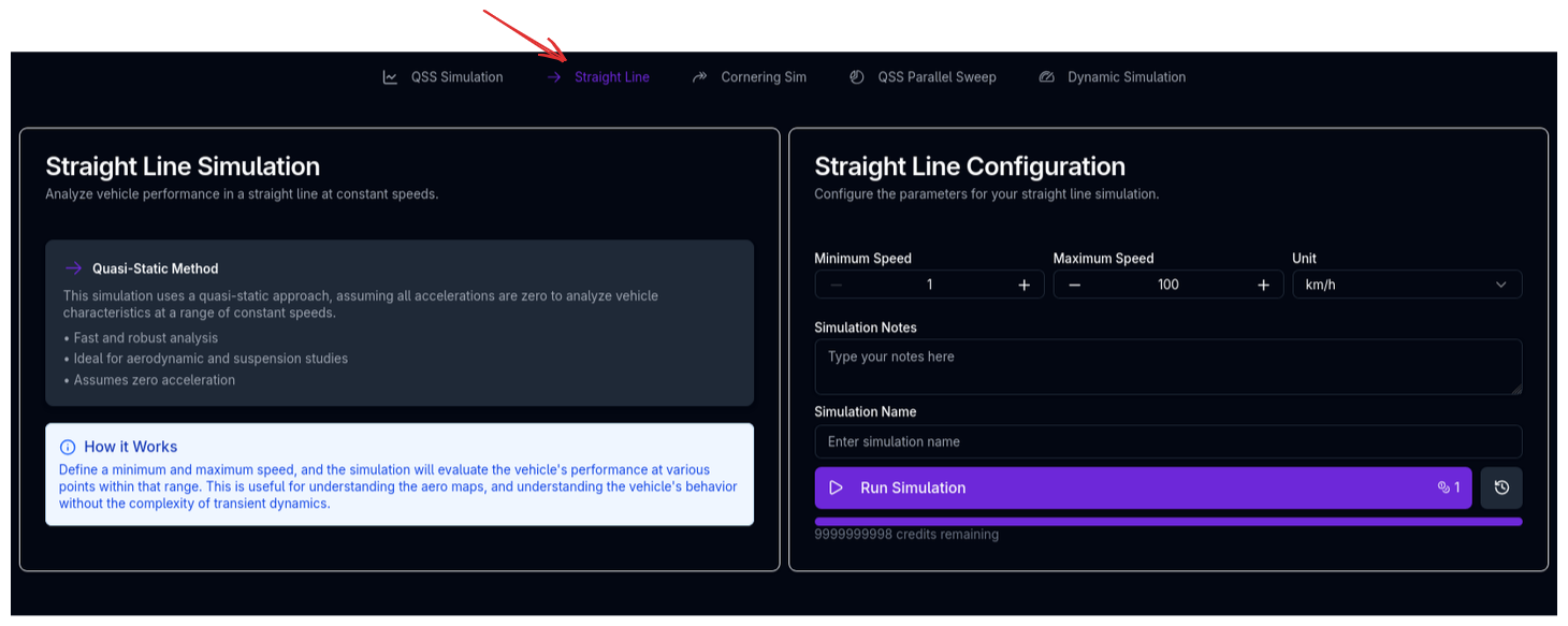
Running the Straight Line Simulation
- Ensure your vehicle setup is complete (chassis, suspension, aerodynamics, tyres at minimum)
- Navigate to the Straight Line simulation page
- The simulation will use the default speed range
- Enter a Simulation Name and optional notes
- Click Run Simulation
Tips & Best Practices
Check Ride Heights First
Before running any lap time or cornering simulation, run a straight line simulation to verify that your ride heights behave as expected across the speed range. If the car drops too much or too little at high speed, your aero balance will be wrong in all subsequent simulations.
Compare Against Aero Data
If you have wind tunnel or CFD data at specific ride heights, use the SLS to verify that the simulation produces consistent ride heights at the relevant speeds. Discrepancies often indicate spring rates that don't match the intended aero platform.
Watch for Bump Stop Engagement
If the ride height curve shows a sudden change in slope (stiffening), the bump stops are engaging. This is expected behaviour at high speed for many cars, but the speed at which it occurs should match the design intent. Adjust spring rates or bump stop gaps if the engagement point is not where you want it.
Evaluate Aero Efficiency
The ratio of downforce to drag (FLift / FDrag, often called L/D or aero efficiency) at your typical straight-line speed tells you how much performance you're paying for in drag. Use this to compare aero configurations before committing to a track simulation.
Ride Heights and Aero Map Range
If the converged ride heights fall outside the range of your aero map at high speed, the aero forces will be clipped within the ride height range specified, which may produce unrealistic results. Ensure your aero map covers the expected ride height range at maximum speed.
Relationship to Other Simulations
The straight line simulation shares the aero-ride height convergence physics with the other QSS-family simulations:
| Simulation | Lateral Accel | Longitudinal Accel | Aero-Suspension Coupling | Powertrain | Tyre-Level Detail |
|---|---|---|---|---|---|
| Straight Line (SLS) | -- | -- | Yes | -- | -- |
| Cornering (CS) | Yes | -- | Yes | -- | Yes |
| Lap Time (QSS) | Yes | Yes | Yes | Yes | -- |
The SLS is the foundation — if the aero platform is wrong here, it will be wrong everywhere. The cornering simulation adds lateral dynamics and full tyre-level detail. The lap time simulation adds the full longitudinal dynamics and powertrain model, but trades tyre-level detail for the speed of the GGV envelope approach.
Related Topics
- Lap Time Simulation (QSS) — Full lap simulation using the same aero-suspension physics
- Cornering Simulation — Adds lateral dynamics and full tyre-level detail
- Aerodynamics Setup — Configure the aero model that drives SLS results
- Suspension Setup — Springs, bump stops, and ride heights that control the aero platform
- Trace View — Visualise straight line simulation results